To enable Bluetooth LE Audio, Bluetooth Core Specification v5.2 introduced Isochronous Streams as the LE transport mechanism for Audio Streams. Isochronous Streams are categorized into two main types: the Unicast or Connected Isochronous Stream (CIS) and the Broadcast Isochronous Stream (BIS). The focus here is on the latter, BIS.
BIS allows Bluetooth LE Audio to cater to broadcast applications where an audio source can broadcast LE Audio to many devices without establishing connections. Examples of such applications include public announcements, hearing aids, sharing music with friends, broadcasting Game Audio during group game play, and activating sound in previously muted public TVs.
To fully grasp how different LE Audio profiles broadcast audio data, one must know a fair amount about BIS. This article explores key concepts of BIS to better understand how it is being used to transform audio sharing and public listening experiences.
What is a Broadcast Isochronous Stream?
BIS is a logical transport used for broadcasting isochronous data, such as audio data, between unconnected LE devices. It is also used to carry control information for stream management.
The key characteristics of BIS include:
- Connectionless Nature: BIS does not require link establishment procedures. This allows any device within range to receive unencrypted data from an Isochronous Broadcaster, the source of the data. Devices that have the encryption key can receive encrypted data too.
- Security: BIS supports both unencrypted streams and streams encrypted with a security key known as the Broadcast_Code.
- Unidirectional Traffic: Data transmission is only from the Isochronous Broadcaster to the Synchronized Receiver(s). There is no bidirectional data transmission. The Isochronous Broadcaster acts as the sender, while the Synchronized Receiver is the receiver.
- Unreliable: BIS has no acknowledgement scheme to facilitate flow control or to guarantee that data has been received. This makes BIS inherently unreliable. However, it supports multiple retransmissions of the same data through Immediate Repetition Count (IRC) and pre-transmissions, which improve reliability, as explained later.
- Flexible Data Rates: BIS can manage data packets of varying sizes. It can also send one or multiple packets per transmission event. This flexibility allows implementers to customize packet size, the number of packets sent during each transmission, and transmission interval timing. As a result, BIS supports a wide range of bandwidths to meet various requirements.
- Allows Isochronous Communication: BIS can transmit time-sensitive data at precise intervals, includes flushing mechanisms, and supports synchronized data reception across multiple Synchronized Receivers, as will be shown later.
What is a Broadcast Isochronous Group?
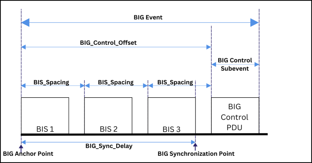
A Broadcast Isochronous Group (BIG) is a collection of one or more BISes. There can be a maximum of 31 BISes in a single BIG. Each BIS within a BIG has its own isochronous flow of data, but all BISes in a BIG share a common timing reference called the BIG synchronization point.
BIG Synchronization Point
The BIG synchronization point is a reference timing point that allows multiple Synchronized Receivers, receiving data from the same Isochronous Broadcaster at different times to synchronize their reception of that data.
For example, consider a mobile phone transmitting stereo music using a BIG with two BISes. One BIS carries music for the left audio channel, while the other carries music for the right channel. These BISes are transmitted sequentially, so the left and right earbuds receive their Audio Streams at different times.
However, because BISes within the same BIG share a reference timing point, audio reception between the left and right earbuds is synchronized. The BIG Synchronization Point ensures that even if one earbud receives its Audio Stream before the other, it will wait until the second earbud has received its stream.
The BIG synchronization point works along with Presentation Delay defined in the Broadcast Audio Profile (BAP) to ensure that Synchronized Receivers present audio simultaneously to the user. For example, left and right audio is made available to the left and right earbuds’ Host for rendering at the same time.
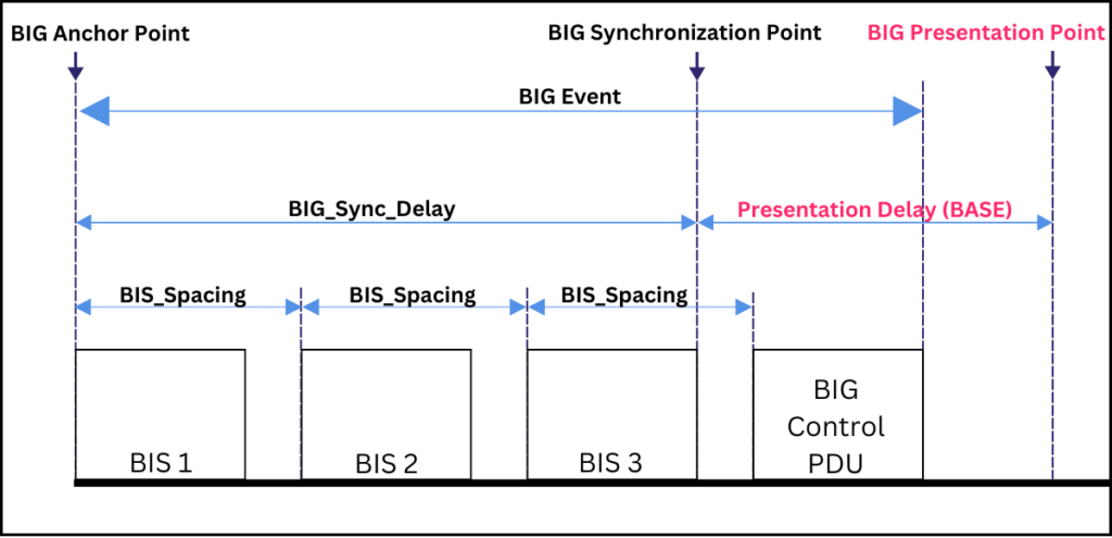
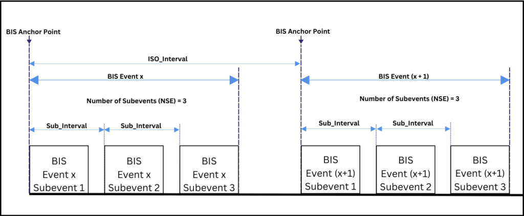
The BIG synchronization point is located at the end of the last BIS subevent in the last BIS event in a BIG. The beginning of the BIG event is called the BIG Anchor point. The time lapse between the BIG anchor point and the BIG synchronization point is specified using the delay parameter, BIG_Sync_Delay, as shown in the figure below.
BIS Timing
Data transmission in a BIS logical transport is through a sequence of BIS events broadcasted at regular intervals. This constant time interval between the BIS event transmissions is called the ISO_Interval, and it ranges from 5 milliseconds to 4 seconds, in increments of 1.25 milliseconds. The start of each ISO_Interval in a BIS event is known as the BIS anchor point.
Each BIS event consists of one or more subevents. A subevent offers an opportunity slot for the Isochronous Broadcaster to transmit a single BIS Data PDU and for a Synchronized Receiver to receive it.
The time between the start of two consecutive subevents in a BIS event is called the Sub_Interval spacing, and it remains constant for the lifetime of the BIS. The total number of subevents in a BIS event is denoted by the Number of Subevents (NSE) parameter.
The BIS PDU
In a BIS, data is sent in the form of Link Layer (LL) Protocol Data Units (PDUs), called BIS Data PDUs. Each BIS PDU consists of a 16-bit header and a payload, which can be up to 251 octets in size. Additionally, there’s an optional MIC (Message Integrity Check) included only when the data is encrypted.
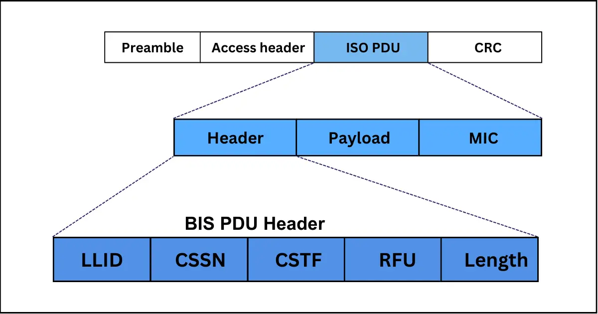
The BIS PDU header contains the following key fields:
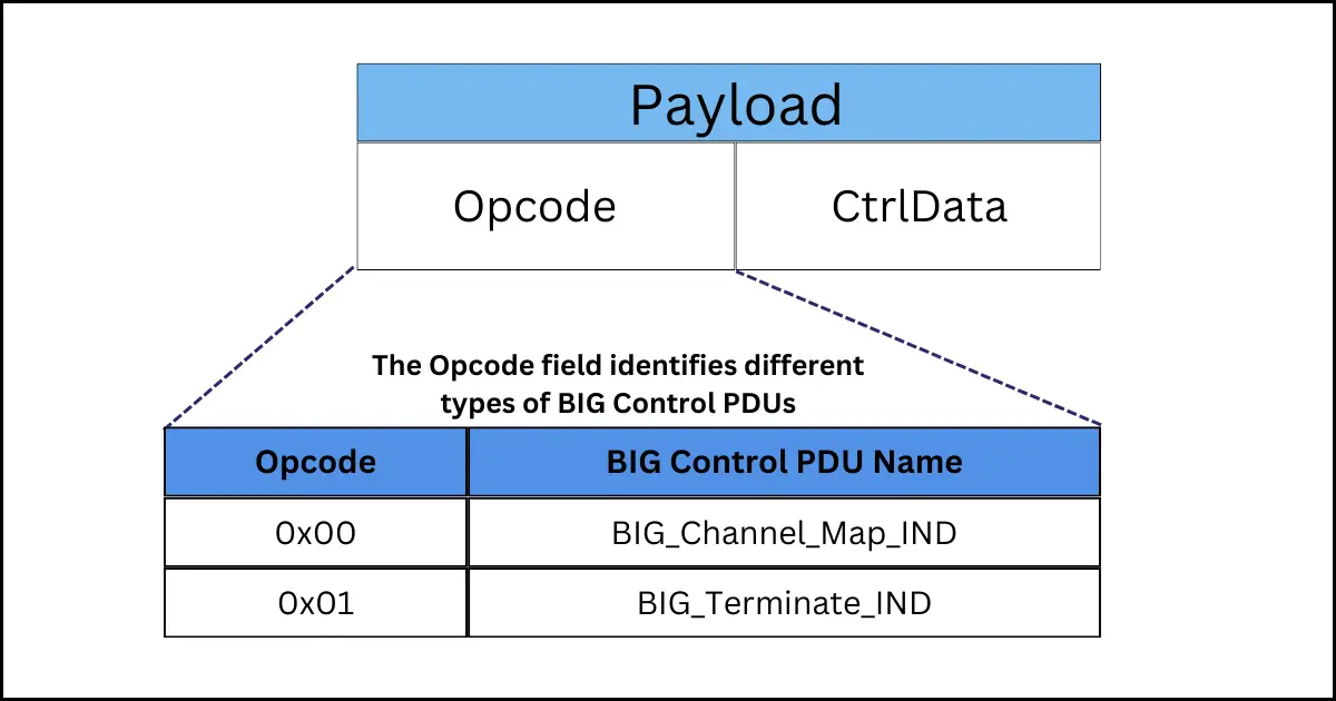
- LLID (Link Layer ID): This field shows whether the payload data is fragmented or complete, framed or unframed, or if the PDU is a BIG (Broadcast Isochronous Group) Control PDU.
- CSSN (Control Subevent Sequence Number): This is used by Synchronized Receivers to identify if a BIG Control PDU is a repeat or a new transmission.
- CSTF (Control Subevent Transmission Flag): This indicates the presence of a control subevent, which provides control information to all Synchronized Receivers.
- Length: It specifies the size of the payload and includes the MIC, if present.
How BIS Improves Reliability of Transmissions
Compared to wired transmissions, wireless transmissions are inherently less reliable. This is especially true in wireless broadcast topologies, where data is transmitted in one direction only, without any acknowledgment of receipt.
BIS, being a broadcast topology, compensates for the lack of an acknowledgment scheme by transmitting the same data multiple times.
During each BIS event, the Isochronous Broadcaster may transmit the same BIS Data PDU multiple times across different subevents. This redundancy increases the likelihood that a Synchronized Receiver, missing a packet in one subevent, will successfully receive it in subsequent subevents.
Also, in the case where pre-transmission is used, the receiver has additional chances to receive the packet in subevents earlier than its scheduled BIS event, as will be explained later.
Additionally, to increase resilience to channel interference, every subevent is transmitted over a different RF frequency, selected using the Channel Selection Algorithm #2.
The arrangement of the transmissions in a BIS event is influenced by two key Controller parameters, the Burst Number (BN), and Number of Subevents (NSE) and, along with a derived metric known as the Group Count (GC):
- BN parameter: It specifies the number of original BIS Data PDUs that can be scheduled for transmission and retransmission. These BIS Data PDUs are grouped and called a ‘burst’. The BN value can range from 0 to 7. A BN of 2, for example, means each burst has two unique BIS Data PDUs, and thus the BIS event uses two subevents for each transmission, and two subevents for each retransmission, if present.
- NSE parameter: It indicates the total number of subevents within a single BIS event. For example, an NSE value of 4 means there are four separate opportunities for transmitting a BIS Data PDU in that event.
- GC parameter: The GC parameter is used to organize the subevents in a BIS event into groups based on the BN value. It is calculated as NSE divided by BN NSE/BN, ensuring each group has enough subevents for a complete burst. The groups are numbered from 0 to GC-1 and transmitted sequentially.
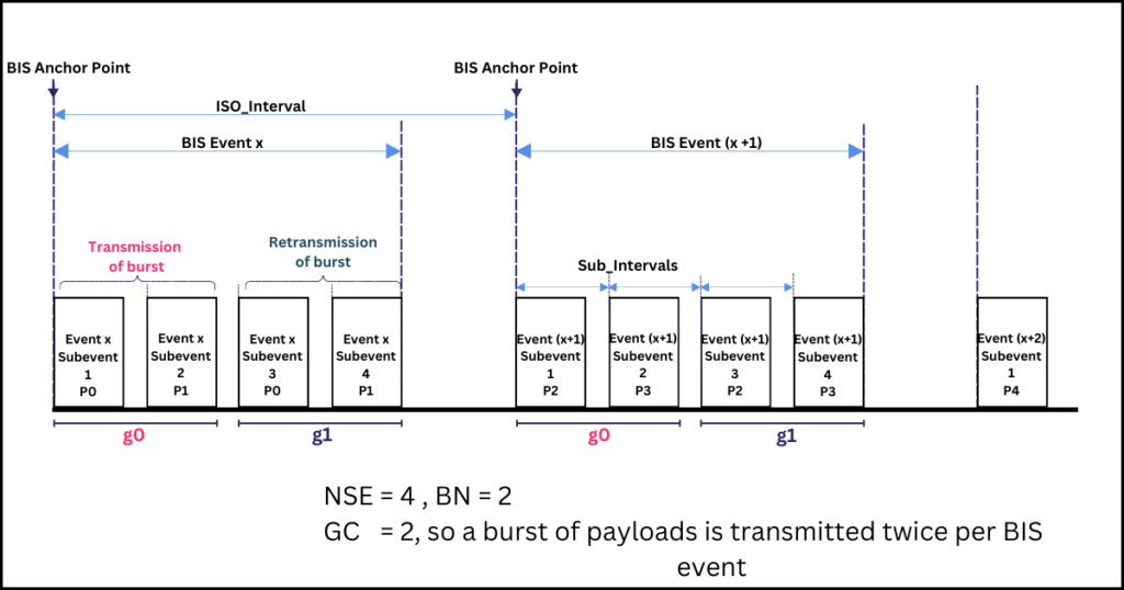
A GC value greater than one means that the BIS event includes redundant transmissions or retransmissions.
The first group, labeled g0, is responsible for transmitting the first instance of a burst of BIS Data PDUs. The subsequent groups focus on either retransmitting the burst initially sent in g0 or pre-transmitting the burst that will be included in the first group of a future BIS event.
Pre-transmissions: Retransmissions Across Multiple BIS events
For each scheduled BIS event, an Isochronous Broadcaster schedules a burst of up to seven new BIS Data PDUs. This burst can be transmitted either in the subevents of the scheduled BIS event or in earlier events.
The Immediate Repetition Count (IRC) parameter indicates how many times a burst of BIS Data PDUs is retransmitted in the subevents of a scheduled BIS event. An IRC value of one or more spreads data loss across subevents, ensuring that if one subevent is missed, the data might still be received in other subevents.
Pre-transmission occurs when a burst of BIS Data PDUs is retransmitted in the subevents of an earlier BIS event than the scheduled one. This approach introduces time diversity, providing additional chances across different BIS events for successful data transmission. It spreads the risk of data loss across multiple BIS events, so that if a single BIS event cannot be received, the data may be received in other BIS events.
Pre-transmission works by dividing the subevents of the current BIS event into groups: some carry transmissions and retransmissions for the current event, while others retransmit data from subevents of group g0 in upcoming BIS events.
To decide which groups do what, the group count parameter is used along with two other parameters:
- Immediate Repetition Count (IRC): It denotes the number of groups which carry data associated with the current BIS event.
- Pre-transmission Offset (PTO): The PTO offset is used to determine the offset of future event(s) whose data will be retransmitted in the current BIS event.
These three parameters are applied on the following rules:
- g < IRC : In the current BIS event, all the group numbers less than the IRC value are used to carry the current BIS event’s data.
- g ≥ IRC : The subevents whose group number is greater than the IRC are used to carry data for future BIS events. Specifically, the data is from future BIS events derived by PTO x (g – IRC + 1) BIS events after the current BIS event.
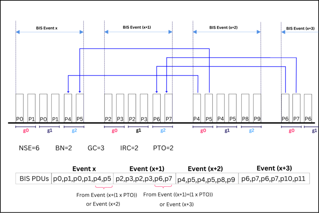
In Figure 6, each BIS event comprises six subevents (NSE=6). These subevents are divided into three groups (g0,g1,g2), with each group containing two subevents, to handle the burst of two payloads (BN=2). With the IRC parameter set at two (IRC=2), the first two groups (g0 and g1) transmit the payloads for the current BIS event, while the third group (g2) transmits payloads for a future event.
To trace the origin of payloads in group g2, the group number ‘2’ is used in the equation:
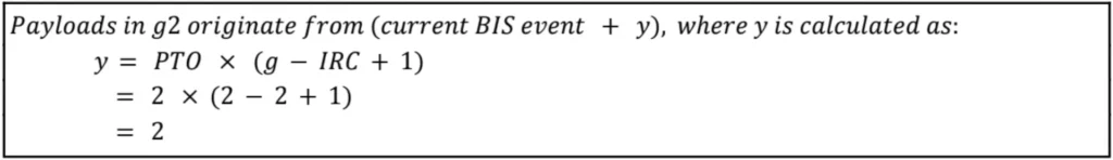
For example, if the current BIS event is labeled event x, then the payloads in its g2 group will be from event (x + 2).

Packing of BISes in a BIG
The Isochronous Broadcaster Host can suggest the preferred method for arranging multiple BISes in a BIG, which can be either sequential or interleaved. This suggestion is included as a Packing parameter in the HCI_LE_Create_BIG command.
It’s important to note that this suggestion is merely a recommendation, and the Controller has the discretion to ignore it. Furthermore, it becomes meaningless when there is only one BIS in the BIG.
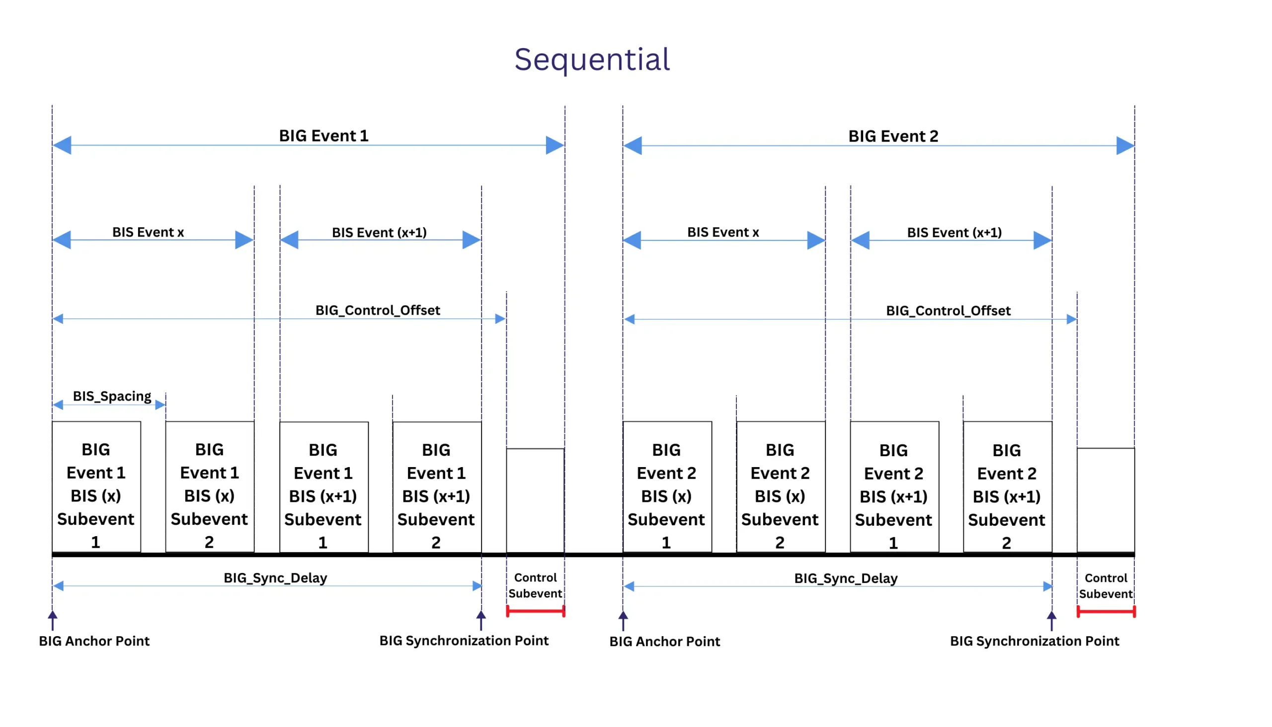
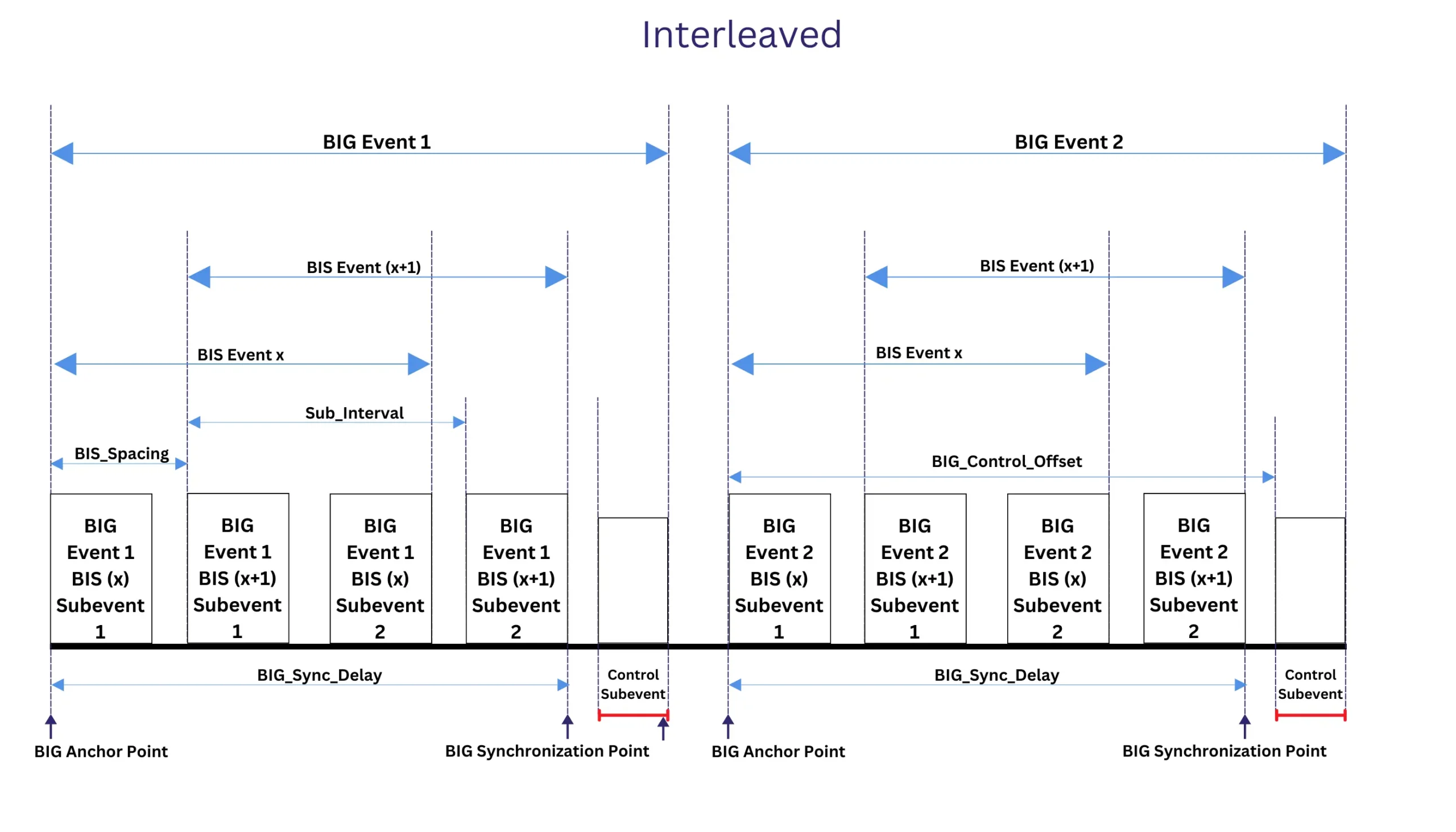
The implemented Packing of the BISes affects the relationship between the BIS_Spacing and the Sub_Interval timing parameters. The BIS_Spacing parameter is the time interval between the start of two consecutive BIS events within a BIG, while the Sub_Interval parameter is the time interval between the start of two consecutive subevents within a single BIS event.
Sequential Packing
When the Controller uses the sequential Packing, all subevents of each BIS are inserted before proceeding to the next BIS. This results in the BIS_Spacing value being greater than the Sub_Interval value, (BIS_Spacing parameter > Sub_Interval parameter ), and the BISes within the BIG occur consecutively, one after the other.
Interleaved Packing
When the Controller uses the interleaved Packing, the subevent of each BIS is inserted in a round robin fashion. This results in the BIS_Spacing value being less than the Sub_Interval value, BIS_Spacing parameter > Sub_Interval parameter, (BIS_Spacing parameter < Sub_Interval parameter), and the BISes within the BIG overlap and interlace.
Control Subevent in a BIG
A BIS event only transports data, while a BIG event can transport both data and control information. Data transmission within a BIG event occurs through BIS event subevents, while control information, such as channel map updates and BIG termination details, is conveyed through the BIG Control PDU delivered by a control subevent.
Note that the presence of a control subevent in a BIG does not change the NSE value or affect the timing of the BIG synchronization point.
Also, whenever a BIG event includes a control subevent, all BIS Data PDUs set their control subevent transmission flag (CSTF) to one. This indicates the presence of control information for Synchronized Receivers.
Each BIG Control PDU has a control subevent sequence number (CSSN) to help Synchronized Receivers distinguish between new and retransmitted control information.
The CSSN starts at one and wraps to zero after reaching seven. It increments at the start of a BIG event that includes the first transmission of a new BIG Control PDU. During retransmissions, the CSSN remains unchanged, and all BISes within a BIG share the same CSSN value.
Control Subevent Timing
Inside a BIG event, there can only be one control subevent, which is always scheduled after the last subevent of the last BIS. The time from the BIG anchor point to the start of the control subevent is called the BIG_Control_Offset, and it is calculated differently depending on whether the BISes are packed sequentially or in an interleaved manner.
- In a sequential packing: The BIG_Control_Offset = Num_BIS*BIS_Spacing
- In an interleaved packing: BIG_Control_Offset = NSE*Sub_Interval
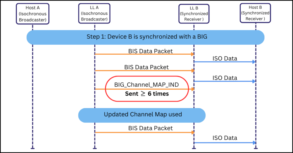
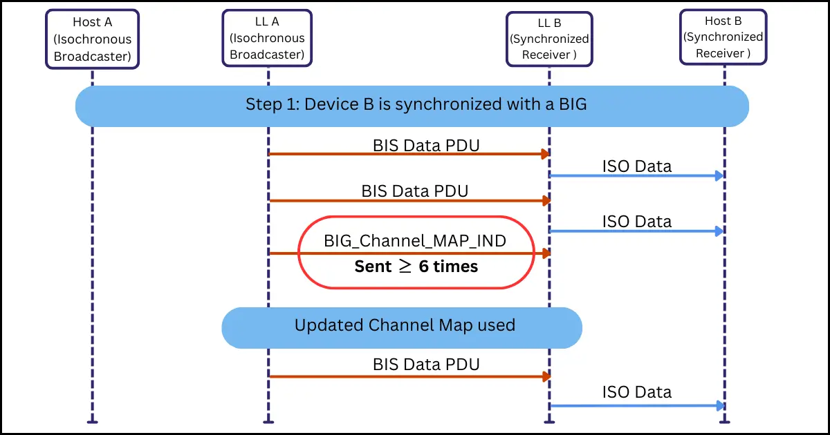
When the Isochronous Broadcaster needs to deliver control information, the control subevent is initially transmitted in six consecutive BIG events as shown in Figure 11 below. Afterward, it may be sent in any subsequent BIG event.
To support the interoperability of how the control information is transmitted, the following Generic Access Profile (GAP) procedures are defined:
- GAP Broadcast_Isochronous_Channel_Map_Update procedure: This procedure allows the Isochronous Broadcaster to transmit a new channel map using the BIG_Channel_Map_IND Control PDU. When a Synchronized Receiver receives the channel map update message, it uses the new channel map when receiving data from the BIG at the specified instant.
GAP Broadcast_Isochronous_Terminate procedure: This procedure allows the Isochronous Broadcaster to terminate a BIG by sending the BIG_ Terminate_IND Control PDU. This PDU lets the Synchronized Receiver(s) know the reason for the termination as well as when the BIG will be terminated.
Control Subevent Timing
Inside a BIG event, there can only be one control subevent, which is always scheduled after the last subevent of the last BIS. The time from the BIG anchor point to the start of the control subevent is called the BIG_Control_Offset, and it is calculated differently depending on whether the BISes are packed sequentially or in an interleaved manner.
- In a sequential packing: The BIG_Control_Offset = Num_BISBIS_Spacing
- In an interleaved packing: BIG_Control_Offset = NSESub_Interval
When the Isochronous Broadcaster needs to deliver control information, the control subevent is initially transmitted in six consecutive BIG events as shown in Figure 11 below. Afterward, it may be sent in any subsequent BIG event.
To support the interoperability of how the control information is transmitted, the following Generic Access Profile (GAP) procedures are defined:
- GAP Broadcast_Isochronous_Channel_Map_Update procedure: This procedure allows the Isochronous Broadcaster to transmit a new channel map using the BIG_Channel_Map_IND Control PDU. When a Synchronized Receiver receives the channel map update message, it uses the new channel map when receiving data from the BIG at the specified instant.
- GAP Broadcast_Isochronous_Terminate procedure: This procedure allows the Isochronous Broadcaster to terminate a BIG by sending the BIG_ Terminate_IND Control PDU. This PDU lets the Synchronized Receiver(s) know the reason for the termination as well as when the BIG will be terminated.
In a BIG event with a control subevent, all BIS Data PDUs have their control subevent transmission flag (CSTF) set to one, indicating the presence of control information for Synchronized Receivers.
Each BIG Control PDU is assigned a control subevent sequence number (CSSN) to help Synchronized Receivers distinguish between new and retransmitted control information.
The CSSN starts at one, wraps to zero when it reaches seven, and increments at the beginning of a BIG event containing the first transmission of a new BIG Control PDU. Importantly, it remains unchanged during retransmissions, and all BISes within a BIG share the same CSSN value.
Encrypted BIG
A BIG transmission can be encrypted or unencrypted. GAP defines security mode 3, which specifies three security levels and their encryption requirements for a BIG transmission.
| Security Mode 3 Levels | Security Requirements |
| Level 1 | No security (no authentication and no encryption) |
| Level 2 | Use of an unauthenticated Broadcast_Code |
| Level 3 | Use of an authenticated Broadcast_Code |
Level 1 allows unencrypted BIS transmissions, accessible to any Synchronized Receiver. In Level 2, an Isochronous Broadcaster uses a 128-bit Broadcast_Code to derive the session key for encrypting a BIG and its BIS(es).
Level 3 provides the highest security, allowing only Synchronized Receivers that receive the Broadcast_Code through an authenticated method to process or decrypt the BIS PDUs in the BIG. If a receiver is unauthenticated, it is recommended that it indicates an error to the user, such as insufficient security for the Broadcast_Code.
For consistency and interoperability, GAP recommends calling the Broadcast_Code the ‘Bluetooth Privacy Code’ in user interfaces. The Broadcast_Code is required to have four to sixteen octets, with a 16-octet code recommended for maximum entropy.
The Bluetooth Privacy Code converts into a 128-bit value using UTF-encoding. The resulting bytes are arranged into 8-bit fields, starting from the least significant bit, with zeros added to the most significant bits if needed for padding.
For example, the Bluetooth Privacy Code string ‘GymTime$2day’ converts to the 128-bit Broadcast_Code value 0x00000000_79616432_24656D69_546D7947.
Broadcast Features Across GAP, HCI, and Link Layer
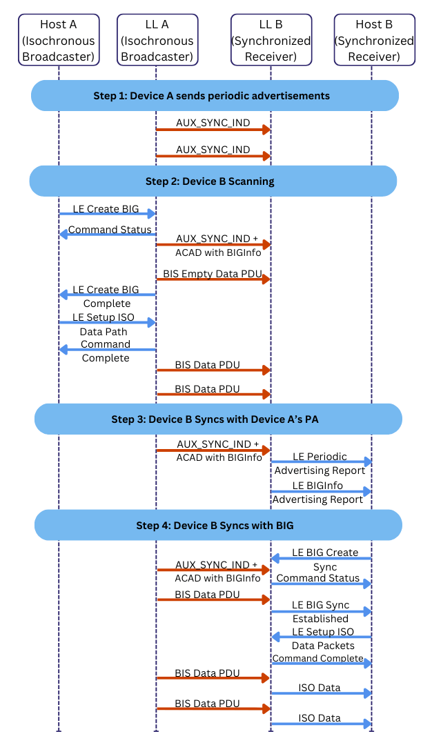
To broadcast data using BISes within a BIG, a device needs to first configure advertising PDUs containing BIG synchronization information and then the isochronous data. This synchronization information is needed for Scanners to achieve synchronization with a BIG that transports relevant broadcast streams.
GAP provides two modes to the GAP Broadcaster to define its behavior during discovery and in the Isochronous Broadcasting State. These modes are:
- GAP Broadcasting Isochronous Synchronizability mode: For transmitting BIG synchronization information in a periodic advertising train(PADV). Each BIG is associated with a PADV that contains BIGInfo [Volume 6, Part B, Section 4.46.11] in its ACAD field [Volume 6, Part B, Section 2.3.4.8]. BIGInfo points to the BIG and provides the necessary data that enables synchronization to it.
- GAP Isochronous Broadcasting mode: For transmitting the isochronous broadcast data.
To create a BIG, the Host of a device sets up and configures the BIG using the HCI_LE_Create_BIG command. The BIGInfo is added to the ACAD field in the PADV, and the BIS are created. The Controller broadcasts a BIS Empty Data PDU, and then sends an HCI_LE_Create_BIG_Complete event to the Host to indicate that the HCI_LE_Create_BIG command has successfully completed and its Link Layer has entered the Isochronous Broadcasting state.
A Controller broadcasting BIS data is in the Link Layer (LL) Isochronous Broadcasting state, and has the LL Isochronous Broadcaster role.
To enable the transmission of in BIS Data PDUs with data, the Host uses the HCI_LE_Setup_ISO_Data_Path command to set up the isochronous data path with codec processing in Controller or Host.
To terminate broadcasting a BIG, the Host uses the HCI_LE_Terminate_BIG command and the Isochronous Broadcaster broadcasts the BIG_ Terminate_IND control PDU.
Synchronizing with a BIG
The GAP provides the GAP Observer role and the GAP Broadcast Isochronous Synchronization Establishment procedure for the Synchronized Receiver to define its behavior in the Synchronization State. The GAP Broadcast Isochronous Synchronization Establishment procedure defines the way for a device to synchronize to a BIG.
To receive broadcast streams, the Host of a device uses the HCI_LE_BIG_Create_Sync command to synchronize to a BIG in the Controller. The Controller of a device enters the Link Layer Synchronization state.
The Synchronization state has two substates. The Controller enters the Synchronizing sub-state to receive synchronization information from the PADV associated with the BIG. After it has used this BIG synchronization information to successfully receive a BIS PDU from the BIG, it enters the Synchronized sub-state and becomes a Synchronized Receiver.
The Host of the Synchronized Receiver uses the HCI_LE_ISO_Data_Path to do codec processing in the Controller or Host on the received broadcast streams. To stop synchronization to a BIG, the Host uses the HCI_LE_BIG_Terminate_Sync command.
| Note: The implementation of BAP for discovering and receiving BIG with BIS carrying broadcast audio data is detailed in the Fundamentals of LE Audio: Periodic Advertising article. |
BAP Device Roles
BAP defines four roles: Broadcast Source, Broadcast Sink, Scan Delegator and Broadcast Assistant.
A Broadcast Source acts as the audio source. It sends a BIG, which includes one or more BISes with broadcast audio data, by implementing the LL Isochronous Broadcaster role. It also sends advertising PDUs with audio announcements, allowing listening devices to discover and receive the broadcast audio data.
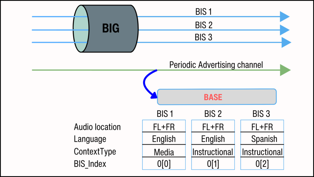
Extended Advertising (EA) PDUs carry the Broadcast Audio Announcements, which may include the Broadcast_ID and Broadcast Name of the BIG. Periodic Advertising (PADV) PDUs include Basic Audio Announcements, which provide configuration details ((BASE data) and synchronization information (BIGInfo) to help devices locate and receive the relevant BIG.
| Note: A Broadcast Audio Source Endpoint (BASE) [BAP 1.0, section 3.7.2.2] and the BIGInfo [Vol 6, Part B, section 4.4.6.11] describe broadcast Audio Stream parameters. The BASE structure is a specialized format for organizing and storing broadcast Audio Stream configuration parameters, such as codec configuration, ContextType (use-case), location of the rendering device, and language. This enables a listening device to identify streams that match its preferences. BIGInfo points to a BIG and enables devices to locate and synchronize with a relevant broadcast Audio Stream. It provides the timing, scheduling, and security details of a BIG, including the number of BISes, NSE, BN, PTO, IRC, ISO_Interval, BIG_Offset from the associated PADV PDU, PHY type, ChannelMap, and encryption parameters for secure BIGs. |
A Broadcast Sink implements the LL Synchronized Receiver role. It discovers and receives the BIG carrying the relevant broadcast Audio Streams. The device scans for EA, which points to PADV pointing to the BIG that contains the BISes transporting the broadcast Audio Streams.
However, scanning for EA PDUs can quickly drain the batteries of low-power devices. To save energy, a device can use the Scan Delegator role to delegate the task of scanning for Broadcast Sources to another device. This process is called Remote Broadcast Scanning. The solicited device takes on the Broadcast Assistant role.
| Note: BAP mandates Scan Delegators for Broadcast Sinks. Therefore, a Broadcast Sink can use a collocated Scan Delegator role to request and receive information about Broadcast Sources. |
The Scan Delegator and Broadcast Assistant use the Broadcast Audio Scan Service to exchange information about the broadcast Audio streams, including the synchronization state to the BISes and the Broadcast_Code to decrypt encrypted BISes.
Broadcast Audio Scan Service
A Scan Delegator implements a BASS instance as a primary service, acting as a BASS server. To solicit other devices for Remote Broadcast Scanning, it advertises the BASS instance by including the BASS UUID in connectable EA PDUs.
The Broadcast Assistant acts as a BASS client. After receiving a solicitation request, it can start scanning on behalf of the Scan Delegator.
BASS has two main characteristics: the Broadcast Audio Scan Control Point characteristic and the Broadcast Audio Scan Receive State characteristic.
The Broadcast Audio Scan Control Point characteristic is writable and allows the Broadcast Assistant (BASS client) to:
- Inform the Scan Delegator (BASS server) when it starts or stops scanning for Broadcast Sources on its behalf.
- Provide information about the Broadcast Source, including its address, Broadcast_ID, Metadata, and Broadcast_Code.
- Request the Scan Delegator to update information about a Broadcast Source or delete the Broadcast Source.
- Request the Scan Delegator to synchronize or stop synchronizing with the PADV associated with a relevant BIG and/or to synchronize or stop synchronizing with a BIG.
The Broadcast Audio Scan Receive State characteristic is a readable characteristic that the Broadcast Assistant (BASS client) can read or receive notifications from.
The Scan Delegator (BASS server) uses this characteristic to share its synchronization status with the PADV associated with a BIG or its BISes. It also indicates whether it has detected an encrypted BIG, is currently decrypting it, requires the Broadcast_Code to start decryption, or if it encountered an incorrect encryption code.
Broadcast Audio Stream State Machine
The Broadcast Source uses the BAP broadcast Audio Stream state machine to manage the BIG used to transport the broadcast audio data. This state machine has three states:
- Idle state: No BIG is configured or set up, so no broadcast Audio Stream is being transported.
- Configured state: The Broadcast Source sets up EA and PA to send audio announcements of the BIG. This includes the BASE data structure, which describes the configuration of each BIS and its content. It specifies exactly what streams the BIG will transmit and their configuration. At this point, audio data is not yet being transmitted.
- Streaming state: BIS Data PDUs with audio data are being transmitted, along with the BIGInfo data (BIG synchronization information).

Broadcast Audio Stream Configuration Procedure
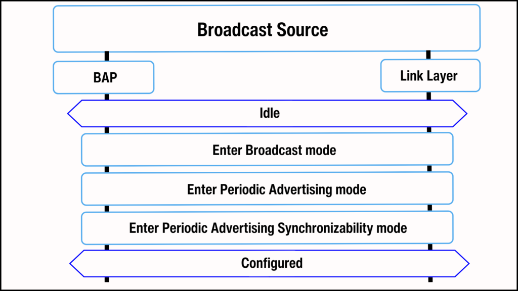
The Broadcast Source implements the BAP broadcast Audio Stream configuration procedure to describe and advertise the BIG with one or more BISes transporting the broadcast Audio Streams. This procedure is implemented as follows:
Step 1: Configure the BASE structure: The BASE data structure describes the broadcast Audio Stream parameters. It includes codec configurations, ContextType MetaData, Audio locations, supported language and other settings defined by an implementation or higher layer specifications.
Step 2 : Enter the GAP Broadcast mode: The Broadcast Source sets up the EA parameters.
Step 3: Enter the GAP PADV mode: The Broadcast Source populates the AdvData field of the AUX_SYNC_IND PADV PDU with the configured BASE data.
Step 4: Enter the GAP Periodic Advertising Synchronizability mode: The Broadcast Source populates the SyncInfo field of the AUX_EXT_IND EA PDU with the periodic advertising synchronization information of the PADV pointing to the BIG.
It also fills the AdvData field of the same AUX_EXT_IND with Broadcast Audio Announcements. The Broadcast Audio Announcements include the Broadcast Audio Announcement UUID and sometimes the Broadcast_ID. The Broadcast Audio Announcement UUID informs listening devices that the EA PDUs point to a PADV associated with a BIG. The Broadcast_ID is a number unique for every BIG. It helps listening devices that do not have a filter to quickly determine if the referenced BIG is relevant to them.
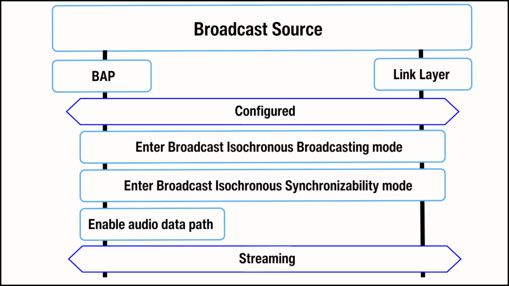
Broadcast Audio Stream Establishment Procedure
The Broadcast Source implements the BAP broadcast Audio Stream establishment procedure to establish a BIG and its BIS(es) to transport the broadcast audio data. This procedure is implement as follows:
Step 1: Enter the GAP Isochronous Broadcasting mode: The Broadcast Source uses the HCI_LE_Create_BIG command to schedule the BIG and its BIS(es).
Step 2: Enter the GAP Broadcast Isochronous Synchronizability mode: The Broadcast Source populates the ACAD field of the AUX_SYNC_IND PADV PDU to transmit the BIG synchronization information or BIGInfo data. This enables the Broadcast Sink or Broadcast Assistant to locate and receive the BIG, and thus the broadcast audio data in its BIS(es).
Step 3: Enable the audio data path: The Broadcast Source uses the HCI_LE_Setup_ISO_Data_Path command to establish the audio data path. Once set up, audio data can be transported as BIS Data PDUs.
Broadcast Audio Stream Disable Procedure
The Broadcast Source implements the Broadcast Isochronous Terminate procedure to transition from the Streaming State to the Configured State. The Broadcast Source initiates this procedure by sending the BIG_TERMINATE_IND control PDU.
The BIG_TERMINATE_IND PDU initiates the LL BIG termination procedure. This procedure stops the transmission of BIS PDUs and BIGInfo.
When the Link Layer of the Broadcast Sink receives a BIG_TERMINATE_IND PDU, it shall stop synchronization with the BIG.
| Note: In the Configured State, the Broadcast Source can still send PADV PDUs related to the BIG, enabling audio transmission to resume at any time. |

Broadcast Audio Stream Release Procedure
The Broadcast Source uses the Broadcast Audio Stream release procedure to transition from the Configured State to the Idle State. It does this by terminating or disabling periodic advertising with the HCI_LE_Set_Periodic_Advertising_Enable HCI command.

Concluding Remarks
Auracast™ and other LE Audio broadcast applications use BIS. This article explained the core concepts of BIS. CIS is used for connection-oriented LE Audio applications. Comparing BIS and CIS can offer useful insights. For more on CIS, see the Fundamentals Series: Connected Isochronous Streams.
References
- “Core Specification 5.4” Bluetooth.com, www.bluetooth.com/specifications/specs/core-specification-5-4/. Accessed 16 Jan 2024.
- “Discovering Auracast™ – The Public Broadcast Profile”, Cloud2GND.com, https://cloud2gnd.com/discovering-auracast-the-public-broadcast-profile/ . Accessed 16 Jan 2024.
- “Public Broadcast Profile 1.0” Bluetooth.com, https://www.bluetooth.com/specifications/specs/public-broadcast-profile-1-0/ . Accessed 16 Jan 2024.
- “Basic Audio Profile 1.0” Bluetooth.com, https://www.bluetooth.com/specifications/specs/basic-audio-profile-1-0/. Accessed 16 Jan 2024.