A Connected Isochronous Stream (CIS) logical transport is a transportation stream optimized for either unidirectional or bidirectional isochronous data transfer between connected Bluetooth Low Energy (LE) devices. It is used in various applications, including gaming, telephony, and media, to provide conversational and streaming audio user experiences.
This article begins by introducing isochronous communication. It explains the structure and function of CIS, and compares it with the Broadcast Isochronous Stream (BIS) transport covered earlier. Understanding CIS and BIS is essential for grasping the Generic Audio Framework, which uses these Isochronous Streams.
Isochronous Communication
“Isochronous” comes from the Greek word “iso” for “same” or “equal” and “chronos” for “time.” It can mean “happening at regular intervals.” Isochronous communication refers to the regular transmission of isochronous data.
Isochronous data is data that arrives at its destination at a precise, fixed rate. Isochronous data is time-bound. It has a finite lifetime after which it becomes invalid.
The Bluetooth v5.2 specification adds Isochronous channels (ISOC) for LE devices. This feature allows for connectionless or connection-oriented transfer of time-bound or flushable data. It also ensures synchronized data reception by multiple receivers.
The LE isochronous physical channel carries the isochronous logical transport. The isochronous logical transport can be unicast (connection-oriented) or broadcast (connection-less). The former, also called Connected Isochronous Stream (CIS), provides point-to-point communication of isochronous data between connected devices in an LE piconet.
A CIS channel is much like the Asynchronous Connection-Oriented (ACL) channel. It provides acknowledgment-based communication.
Furthermore, each CIS channel has an ACL connection. Once two devices establish a connection (an ACL connection exists between them), the Central device may request to set up an isochronous connection (CIS channel). The peer device that accepts or rejects the request is known as the Peripheral device.
The CIS channel carries the isochronous user data. The ACL connection carries the Link Layer (LL) messages to setup and control the CIS. The ACL also provides the timing reference for scheduling CIS events on the CIS channel once it’s established.
Therefore, if for any reason, the ACL connection is lost, all the CISes associated with it get terminated.
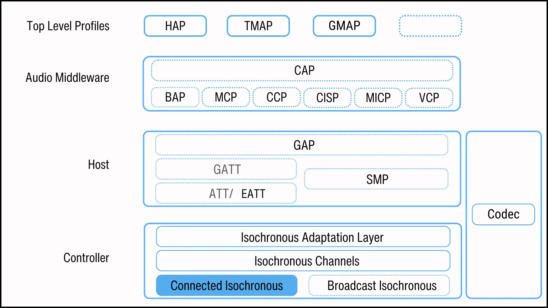
The BIS logical transport, on the other hand, establishes a one-to-many topology, enabling one device to broadcast isochronous data to many. The sender is the Isochronous Broadcaster, and the receivers are Synchronized Receivers. A BIS channel is unidirectional, sending data only from the Isochronous Broadcaster.
Each BIS channel is associated with a periodic advertising train (PADV). The PADV helps listening devices to find and sync to the BIS. To get the broadcast data from the BIS, the listening device must first get the BIS’ synchronization information from PADV and become a Synchronized Receiver.
The PADV and BIS can be enabled and disabled independently. Once devices have synchronized to a BIS or multiple BISes, an Isochronous Broadcaster can stop the PADV transmitting their synchronization information.
Both CIS and BIS channels offer the flexibility of transmitting data securely (encrypted) or openly (unencrypted). Both channels are subdivided into regular time units called isochronous events. Each event is further divided into one or more subevents. Each subevent corresponds to a different radio channel and it is used to transmit isochronous packet data units (PDUs). Flushing mechanisms are used to remove expired data from the channels.
Additionally, both CIS and BIS use isochronous groups—Connected Isochronous Group (CIG) for CIS and Broadcast Isochronous Group (BIG) for BIS—to provide a common timing reference necessary to synchronise data reception across the multiple independent receivers.
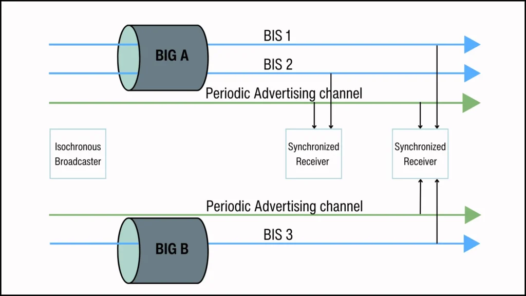
Figure 3 shows a CIG with two CIS Streams. A CIG allows the Central device to set up and group several CIS channels. These channels are independent but have time correspondence at the application layer.
For example, for the CIG in Figure 3, one channel could carry a CIS Stream for left audio. The other could stream the right audio. Or, both channels could carry CIS Streams for the same audio but in different languages.
The Peripheral devices receiving CISes from the same CIG are expected to use the CIG’s timing information to synchronize their data reception. This ensures they present data to their Hosts at the same time. This setup is useful for applications such as multi-stream audio on truly wireless earbuds.
CIS PDUs
In a CIS channel, data is transmitted via CIS Data PDUs, containing isochronous user data, or CIS Null PDUs, which carry no data and provide an acknowledgement.
Each PDU comprises a 16-bit header and a payload up to 251 octets, with an optional Message Integrity Check (MIC) for encrypted data.
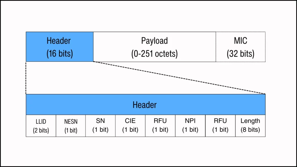
The CIS PDU header contains the following key fields:
- LLID (Link Layer ID): This field indicates whether the payload data is fragmented or complete and specifies if it is framed or unframed. In a CIS Null PDU, the LLID is reserved for future use (RFU).
- NESN and SN (Next Expected Sequence Number) and (Sequence Number): These fields work together to provide a system for acknowledgements and a method to ensure the correct ordering of received packets at the Link Layer (LL). In a CIS Null PDU, the SN is RFU.
- CIE (Closed Isochronous Event): It is used by the Central or Peripheral devices to close CIS events early.
- NPI (Null Payload Indicator): Differentiates between CIS Data and CIS Null PDUs. It is set only in the latter.
- Length: It specifies the size of the payload and includes the MIC, if present.
Acknowledgement and Flow Control
The Central and Peripheral devices manage packet sequence and acknowledgments using the 1-bit SN and NESN fields in the CIS PDU header. Both fields work by incrementing from 0 to 1 and then back to 0 to track and confirm packet order and receipt.
The SN field numbers packets in sequence. For instance, sending a packet with SN 0 indicates the next will be SN 1. This alternation helps the receiver track the sequence. The NESN field tells the sender the sequence number of the next packet the receiver expects to receive.
The combination of SN and NESN provides a simple yet effective way to manage acknowledgments and flow control:
- Acknowledgement: The receiver uses NESN in its response to acknowledge the receipt of a packet with a specific SN. If the sender gets a response with NESN different from the SN of the last packet it sent, it knows the previous packet was successfully received.
- Flow Control: This mechanism also inherently provides flow control. If the sender does not receive an acknowledgment (in the form of an NESN not matching with the SN of the last sent packet), it understands that the last packet might not have been successfully received and can resend it. This ensures that no new data overwhelms the receiver before it successfully receives the previous data.
The following figure describes how it works:
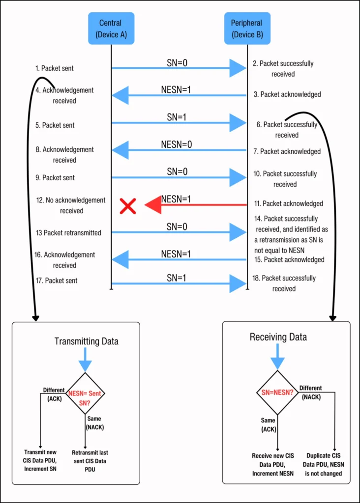
In Figure 5 above, both the Central and the Peripheral compare the SN and the NESN upon receiving a packet. This comparison is to either acknowledge the last CIS PDU sent by the peer or to request a resend of the last CIS PDU.
When the Peripheral receives a CIS PDU with the expected SN (where the SN matches the NESN), it responds with a CIS PDU whose NESN is the opposite of the received packet’s SN. It does this to confirm receipt and show it’s ready for the next packet.
On the other hand, if the Peripheral receives a CIS PDU with an unexpected SN (where the received SN differs from the NESN), it treats the packet as a duplicate CIS PDU, and the NESN remains unchanged.
On the Central side, if the NESN in the Peripheral’s response differs from the SN in the last sent CIS PDU, this means the Peripheral has successfully received the last sent CIS PDU. The Central then increments its SN and sends the next CIS PDU.
But, if the Central gets no response from the Peripheral or gets a response where the NESN is the same as the SN of the last sent CIS PDU, it is a non-acknowledgement (NACK). The Central then resends the last sent CIS PDU.
CIS Structure
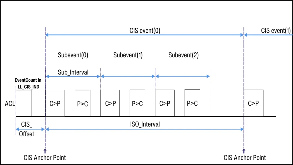
Data transmission within a CIS channel occurs through a series of regularly scheduled CIS events. The CIS events have a constant time interval, called the ISO_Interval, separating them. The ISO_Interval ranges from 5 milliseconds to 4 seconds in 1.25 millisecond increments. The start of each ISO_Interval during a CIS event is the CIS anchor point.
A CIS event has one or more subevents. They transmit and, if needed, retransmit a CIS PDU. Each subevent has two transmission opportunities: the first is the opportunity for the Central to send a single CIS PDU to the Peripheral, and the second is for the Peripheral’s response. The ‘NSE‘ parameter shows the total number of subevents in a CIS event.
The time between successive subevents is the Sub_Interval spacing. It is determined when the CIS is established and remains the same afterwards. For CIS events with only one subevent, the Sub_Interval spacing is zero, and for CIS events that have multiple subevents, it ranges from 400 microseconds to less than the ISO_Interval.
The CIS channel uses the Channel Selection Algorithm #2. It selects a different radio frequency channel for each subevent to reduce interference.
The Link Layer maintains a 39-bit event counter called cisEventCounter. It is set to zero in the first CIS event. Each CIS event then increments it by one. It is also used as an input to the Channel Selection Algorithm #2.
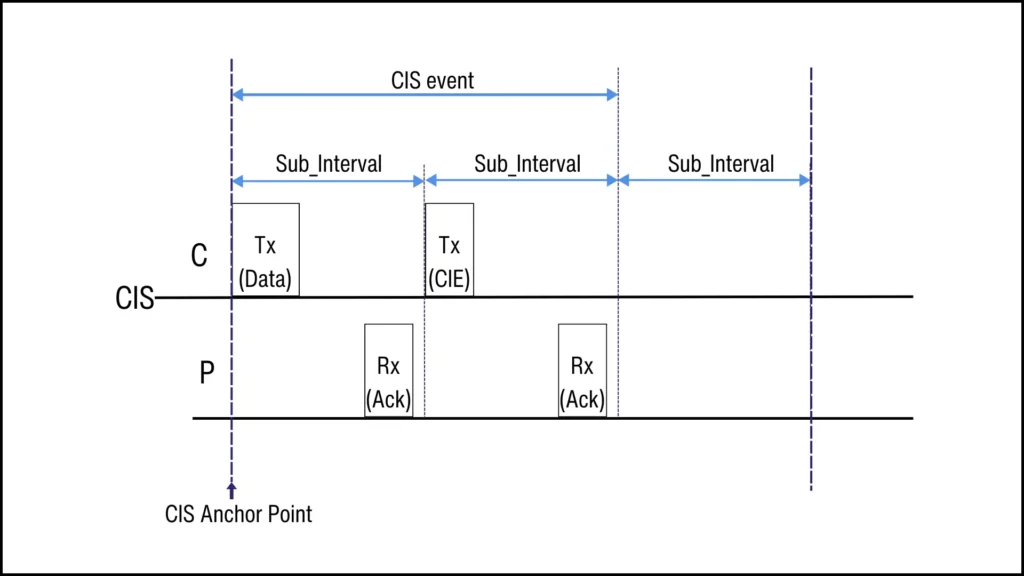
Closing CIS Events Early: CIE
The CIS PDU header has a ‘Close Isochronous Event (CIE)’ bit, which can be used by the Central or Peripheral device to end an isochronous event early when additional retransmissions are unnecessary. This saves energy and optimizes the use of the radio spectrum.
For example, in a unidirectional CIS event, if the Central receives acknowledgements for all the event’s scheduled PDUs but some subevents are left, it can end the CIS event early by sending a CIS NULL PDU with a CIE set to 1.
This tells the Peripheral that no more payloads will come from the Central in that event. So, the Peripheral can use the free airtime for other radio applications or it can go to sleep.
Bidirectional CISes
In a unidirectional CIS channel, only the Central or the Peripheral can send data, not both. Response packets are CIS Null PDUs. They are used to either acknowledge the last CIS PDU or request a retransmission.
In contrast, a bidirectional CIS allows data transmission from both the Central and the Peripheral. Data flow can be symmetrical or asymmetrical in PDU size and PHY choice. Response packets can include data. Both directions use NESN and SN bits to acknowledge received packets.
CIS Robustness: BN, FT, and NSE
The robustness of a CIS channel is significantly influenced by the Burst Number (BN), Flush Timeout (FT), and Number of Subevents (NSE) parameters.
| Parameter | Definition |
| Burst Number (BN) | BN refers to the number of new CIS PDUs scheduled for transmission and retransmission in a CIS event. BN shall be between 0 a$nd 7. |
| Flush Timeout (FT) | FT is the maximum number of ISO_Intervals over which a CIS PDU may be transmitted (and retransmitted) before it expires and is flushed. FT shall be between 1 and 255. |
| Number of Subevents (NSE) | Total number of subevents in a CIS event. A subevent is a transmission opportunity in a CIS event. |
A CIS event can schedule to transmit one or more CIS Data PDUs. This is known as a ‘burst’. The number of packets that make up the burst is indicated by the BN.
Each CIS event is divided into subevents. In these subevents, the Central transmits a CIS PDU, and the Peripheral responds. This acknowledgment-based communication enhances the reliability of packet delivery by confirming receipt or prompting the retransmission of lost or incorrectly received packets.
To further improve reliability, a CIS event can have more subevents than the number of data packets in a burst. This allows for retransmissions. For example, a CIS event with a two-packet burst (BN=2) and five subevents (NSE=5) has three extra chances for retransmissions, if necessary.
A CIS channel also supports a flushing mechanism. In this, each CIS Data PDU in a CIS event gets assigned a Flush Timeout (FT) interval. FT determines how long a CIS PDU is retained for transmission and retransmission before being discarded.
Both the Central and Peripheral monitor the FT interval for each CIS PDU. The interval starts at the anchor point of an ISO_Interval when the CIS PDU is first scheduled for transmission and reception, and expires at the flush point.
The flush point occurs after “U” subevents. The Link Layer sets the counter, “cisEventCounter ”, of the CIS PDU’s scheduled event to (E + FT – 1). The formulas for calculating “E” and “U” are in the Core specification, version 5.4, Volume 6, Part B, section 4.5.13.5.
- E = floor (cisPayloadCounter ÷ BN)
- U = NSE – floor (NSE ÷ BN) × (BN – 1 – cisPayloadCounter mod BN)

The transmitting device, either a Central or a Peripheral, transmits and retransmits an unacknowledged CIS Data PDU until its flush point is reached, after which the PDU is flushed.
Similarly, when the receiving device does not successfully receive a CIS Data PDU during its scheduled subevent, it continues to listen for that same PDU until the flush point is reached. After that, it awaits receipt of the next CIS Data PDU.
Consider a CIS setup as shown in Figure 9. This configuration provides four transmission opportunities per CIS event (NSE=4). Two new CIS Data PDUs are scheduled for transmission per CIS event (BN=2). Each PDU must be sent within one ISO_Interval (FT=1) or it will be discarded.
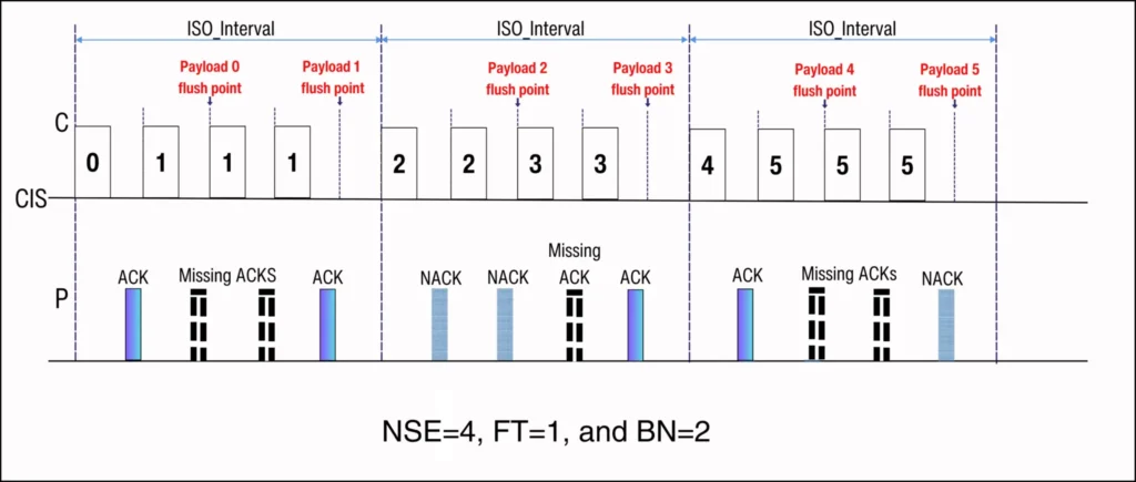
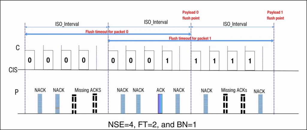
Figure 10 demonstrates the effect of increasing FT to 2. Increasing the FT extends the packets’ retransmissions across multiple CIS events. In this example, the NSE is at 4 and the BN is at 1. A packet (e.g., payload 0) can be transmitted and retransmitted up to 8 times across two ISO_Intervals (FT=2).
CIG Structure
A Connected Isochronous Group (CIG) is a collection of one or more CISes. A maximum of 31 CISes are allowed per CIG.
Each CIG is identified by a CIG_ID, and each CIS within the CIG is given a CIS_ID number. The CIS_ID has meaning at the Host level, but is not used by the Link Layers.
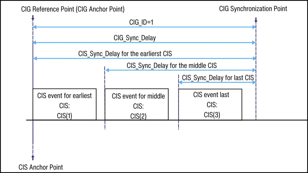
A CIG event begins at the CIG Reference point, which may be coincident with, but can not be later than the anchor point of the earliest CIS of the CIG. A CIG event ends at the CIG Synchronization point, which may be coincident with, but can not be earlier than the end point of the last subevent of the last CIS of the CIG event.
The time lapse between the CIG Reference point and the CIG Synchronization point is the CIG_Sync_Delay. Each CIS has a CIS_Sync_Delay which is equal to the CIG Synchronization point minus the offset from the CIG reference point.
CIG Synchronization point
A CIG Synchronization point is a common timing reference for all CISes in the CIG. It helps the Central synchronize data capture across multiple Peripherals.
As shown in Figure 11 above, for the Peripherals to reconstruct the common CIG Synchronization point, the member CISes are assigned a CIS_Sync_Delay value in a tiered manner. The first CIS in the sequence gets the longest delay, and each subsequent CIS, moving closer to the synchronization point, is given a slightly shorter delay.
This tiered delay system allows the Peripheral that receives the earliest CIS to delay presenting it to its Host until the final CIS in the group is received. This enables all the CISes to be presented to their Hosts at the same time for rendering or processing.
Packing in a CIG
CISes within a CIG can be scheduled to occur either sequentially or in an interleaved manner. The Central’s Host suggests the scheduling preference, called the Packing parameter, to the Controller. It does this via the HCI_LE_SET_CIG parameters HCI command. However, the Controller has the discretion to disregard this suggestion.
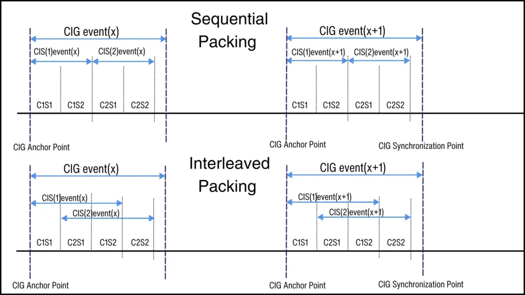
As illustrated in Figure 12, Sequential Packing arranges the CISes within a CIG to occur consecutively, meaning the first subevent of CIS(2) follows the last subevent of CIS(1). In contrast, Interleaved Packing allows the CISes to be interleaved.
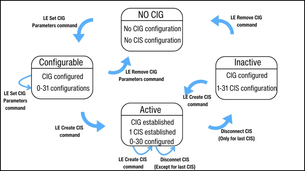
CIG State Machine
The Central device has a CIG state machine that manages a CIG and its constituent CISes through three states:
- Configurable CIG State: This is where all the CISes that make up a CIG are defined. This configuration is performed by the Central device’s Host using the HCI_LE_Set_CIG_Parameters command.
- Active CIG State: This is where one or more of the configured CISes are enabled. The Central’s Host moves the CIG to the active state using the HCI_LE_Create_CIS command.
- Inactive CIG State: A CIG goes inactive when all CISes are disconnected. It can go back to the active state by re-establishing any one of its CISes using the HCI_LE_Create_CIS command.
Features Across GAP, HCI, and LL
The Generic Access Profile (GAP) assigns specific roles to devices involved in establishing ACL connections associated with Connected Isochronous Streams. For a device initiating the connection, its Host assumes the GAP Central role, while its Controller takes on the Link Layer Central role. The Host provides parameters for CIS setup during the Connected Isochronous Central Establishment procedure.
Conversely, the Host of a device accepting a connection adopts the GAP Peripheral role, with its Controller assuming the Link Layer Peripheral role. This device’s Controller receives a CIS establishment request from the Central. The Host, acting in the GAP Peripheral role, has the option to accept or reject this request as part of the Connected Isochronous Stream Peripheral Establishment procedure.
As illustrated in Figure 14, establishing a CIS channel involves a sequence of HCI commands and Link Layer messages exchanged between the connected devices.
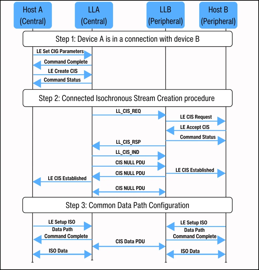
Step 1: Connected Isochronous Group Setup
The Central’s Host uses two HCI commands to tell its Controller about each CIG. The first command is HCI_LE_Set_CIG_Parameters HCI command [Vol 4, Part E, 7.8.97]. It configures a CIG and its CISes.
Below is a summary of the CIG parameters the Host provides. Italicized parameters are just suggestions, which the Controller might not follow.
| Parameter | Description |
| CIG_ID | Assigned by the Central’s Host |
| SDU_Interval_C_To_P | Time interval between SDUs generated from the Central’s Host |
| SDU_Interval_P_To_C | Time interval between SDUs generated from the Peripheral’s Host |
| Worst_Case_SCA | Worst case sleep clock accuracy of all of the Central’s in the CIG |
| Packing | Preferred Packing (sequence or interleave) |
| Framing | Framed if set to 1, otherwise up to the Controller on a per CIS basis. |
| Max_Transport_Latency_C_To_PMax_Tranport_Latency_P_to_C | Maximum transport latency for each direction |
| CIS_Count | The number CISes in the instance of this command |
| CIS_ID[i] | Unique ID for each CIS in this CIG |
| Max_SDU_C_To_P[i]Max_SDU_P_To_C[i] | The maximum sizes of SDUs from the Central’s and Peripheral’s Hosts. |
| PHY_C_To_P[i]PHY_P_To_C[i] | Bitfield indicating possible PHYs to use for each direction. If more than one bit is set, the Controller decides. |
| RTN_C_To_P[i]RTN_P_To_C[i] | The preferred number of retransmissions in each direction. The Controller can ignore this. |
It’s important to note that the Central’s Host cannot specify the BN, FT, and NSE parameters for CIS directly. Instead, the Controller derives these values based on the Host’s inputs regarding maximum transport latency, maximum SDU size, and SDU interval, tailoring them to best fit the operational context.

After setting up the CIG, the Central’s Controller confirms with a Command Complete event. The Central’s Host then uses the HCI_LE_Create_CIS command to establish the proposed CIS.
To this command, the Central’s Controller replies with an HCI Command Status event, showing the command is underway. This procedure status stays pending until the CIS Creation Procedure finishes and the CIS is established.
Step 2: Connected Isochronous Stream Creation Procedure
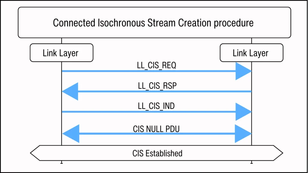
To establish the proposed CIS, the Central’s Link Layer initiates the Connected Isochronous Stream Creation procedure by sending the LL_CIS_REQ Control PDU to the Peripheral.
Control PDUs used in the LL CIS Creation Procedure
The Connected Isochronous Stream Creation procedure consists of the exchange of the following Link Layer Control PDUs between the Central and the Peripheral devices.
- LL_CIS_REQ: It is issued by the Central device to the Peripheral. This PDU contains the CIS configuration parameters suggested by the parameters provided by the Central’s Host.
- LL_CIS_RSP: This response PDU is sent from the Peripheral to the Central to acknowledge the acceptance of the CIS setup request.
- LL_CIS_IND: It is issued by the Central to the Peripheral. It provides CIS timing parameters that help a Peripheral synchronize its data reception with other Peripherals receiving a CIS from the same CIG.
Accepting or Rejecting the Proposed CIS
When the Peripheral’s Link Layer gets the CIS request (LL_CIS_REQ PDU), it can reject invalid requests right away. Or, it can alert its Host using the HCI_LE_CIS_Request event.
If alerted, the Peripheral’s Host implements the GAP Connected Isochronous Peripheral Establishment procedure and tells the Link Layer to accept or reject the CIS.
Accepting the Proposed CIS
As shown in Figure 14, the following exchanges occur when the Peripheral accepts the creation of the proposed CIS:
- The Peripheral’s Host sends the LE Accept CIS command to the Peripheral’s Link Layer (Controller). This command signals it to accept the CIS.
- The Peripheral’s Link Layer then sends the LL_CIS_RSP Control PDU to the Central’s Link Layer (Controller).
- Upon receiving the LL_CIS_RSP Control PDU, the Central’s Link Layer can either:
- Cancel the CIS and send the LL_REJECT_EXT_IND Control PDU with a reason code, or
- Stop its procedure’s response timeout timer, create the CIS, and send the LL_CIS_IND Control PDU.
- Once the Peripheral’s Link Layer receives the LL_CIS_IND Control PDU, it stops its procedure’s response timeout timer and proceeds to create the CIS.
- The Peripheral considers the CIS established when it receives a CIS Null PDU from the Central and sends the LE CIS Established event to its Host.
- The Central considers the CIS established when it receives a CIS Null PDU from the Peripheral and sends the LE CIS Established event to its Host.
After the CIS channel is established, it can only transmit empty PDUs (CIS Null PDUs). Data can only be transmitted after the audio path has been added to the CIS.
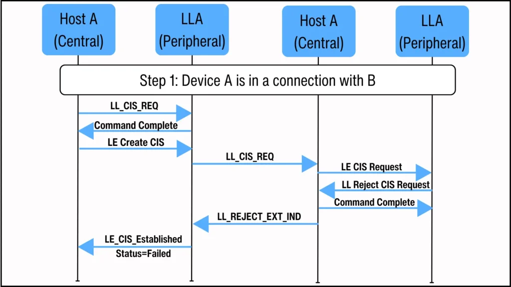
Failure to Create the Proposed CIS
To reject the proposed CIS, the Peripheral’s Link Layer can send an LL_REJECT_EXT_IND message directly, or the Peripheral’s Host can command the Link Layer to send it via the HCI Reject CIS Request command.
This HCI Reject CIS Request command specifies which CIS is being rejected and why. The reason is included in the LL_REJECT_EXT_IND message that the Controller sends out.
Similarly, upon receiving the LL_CIS_RSP Control PDU, the Central’s Link Layer can cancel the CIS creation and send the LL_REJECT_EXT_IND Control PDU with a reason code.
Ongoing CIS Termination
The LL_CIS_Terminate_IND Control PDU is used by either the Central or Peripheral to terminate an ongoing CIS. It identifies the specific CIS to be terminated and provides an ErrorCode explaining the termination reason to the peer device.
Step 3: Common Audio Data Path Configuration
Before using the newly established CIS channel, the Central and Peripheral must add an isochronous data path to the CIS for communication between the Host and the Controller.
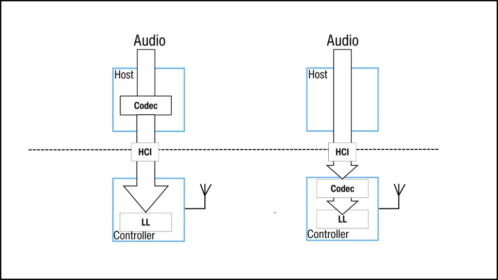
They use the HCI LE Setup ISO Data Path command to set up the data path, including its direction and transport, and optionally configure a codec for the path.
The direction of the data path is either “Input” or “Output”. “Input” means that data flows from the Host to the Controller. “Output” is the opposite; it means that data flows from the Controller to the Host.
For example, when using a CIS for unidirectional music stream from device A to device B. The Host A sets up an input data path to send data from itself to Controller A, which then transmits the data over the air. In device B, Host B sets up an output data path to receive data from Controller B.
In the case of bidirectional communication, the CIS can be associated with two data paths. One “Input” to allow data to flow from the Host to the Controller when a device sends it, and the other “Output” to allow data to flow from the Controller to the Host when it is received.
The data path can be over the HCI transport, as seen in Figure 17, or over a vendor-specific transport interface, such as a PCM interface.
After the data paths are successfully set up, the CIS Data PDUs can be transmitted over the CIS.
CIS and BIS
The table below summarizes the comparison between CIS and BIS:
| Parameter | BIS | CIS |
| Isochronous Communication | -Transmits time-sensitive data at precise intervals between unconnected LE devices. -Incorporates flushing mechanisms and enables synchronized data reception across multiple receivers. | -Transmits time-sensitive data at precise intervals between connected LE devices. -Incorporates flushing mechanisms and enables synchronized data reception across multiple receivers. |
| Channel Use | -It supports adaptive frequency hopping with Channel Selection Algorithm #2. -It supports the Channel Map Update procedure. | -It supports adaptive frequency hopping with Channel Selection Algorithm #2.-It supports the Channel Map Update procedure. |
| Flexible Data Rate | -It supports variable packet sizes and subevent counts. This enables a variety of data rates, latencies, and retransmissions. | -It supports variable packet sizes and subevent counts. This enables a variety of data rates, latencies, and retransmissions. |
| Casting | -It supports only unidirectional traffic from the Isochronous Broadcaster to the Synchronized Receiver. | -It supports unidirectional and bidirectional data flow between peer devices, allowing for symmetric or asymmetric data flows. |
| Reliability of delivery | -It is inherently unreliable because it lacks an acknowledgment protocol. This protocol would confirm data receipt or request retransmission of erroneous packets. -It improves reliability through the unconditional retransmission of identical packets. -Pretransmissions are used to improve the time-diversity of retransmissions. | -It uses a Automatic Repeat reQuest (ARQ) protocol to resend erroneous packets. It resends them until it either succeeds or reaches a flush point. Then, it flushes the isochronous data packet. -Retransmissions are initiated when packets are not acknowledged or are NACKed. |
| Control Information | A BIG event can transport both data and control information. Data is sent through BIS event subevents, while control information is sent as a BIG Control PDU in a BIG control subevent. | A CIG event only transports isochronous data. The CIG uses the ACL connection to transport control information. |
| LE Power Control Feature | It does not support the LE Power Control feature. | -It supports LE Power Control using the ACL connection associated with it. The LE Power Control feature adds the possibility to control transmit power. This improves power management, link quality and it minimizes interference. |
| Security | Uses the LE Security Mode 3. | Encryption status of a CIS is the same as the encryption status of the associated ACL. |
Concluding Remarks
This article describes CIS, which enables isochronous transmission of flushable data between connected LE devices. It explains CIS channel’s structure and its various PDUs, as well as the factors affecting its robustness. These include BN, FT, and NSE parameters. It also discusses CIG and how it groups time-related CIS streams.
Furthermore, the article describes the sequence of HCI commands and LL messages sent between the Central and Peripheral devices in a CIS connection. It also compares CIS with BIS. For more on BIS, see the ‘Broadcast Isochronous Stream’ article in the Fundamental Series.
References
- “Core Specification 5.4” Bluetooth.com, www.bluetooth.com/specifications/specs/core-specification-5-4/. Accessed 16 Jan 2024.
- “Discovering Auracast™ – The Public Broadcast Profile”, Cloud2GND.com, https://cloud2gnd.com/discovering-auracast-the-public-broadcast-profile/ . Accessed 16 Jan 2024.
- “Public Broadcast Profile 1.0” Bluetooth.com, https://www.bluetooth.com/specifications/specs/public-broadcast-profile-1-0/ . Accessed 16 Jan 2024.
- “Basic Audio Profile 1.0” Bluetooth.com, https://www.bluetooth.com/specifications/specs/basic-audio-profile-1-0/. Accessed 16 Jan 2024.