Channel Sounding (CS) is a new positioning feature that helps a Controller characterize the propagation path between itself and a connected peer device for distance estimation. It uses phase-based ranging (PBR) and round-trip timing (RTT) ranging methods. The measurements collected through a CS procedure are processed using a distance-measuring algorithm chosen by the implementer.
CS is expected to be useful in areas like mobile guide and navigation, asset tracking, indoor navigation, localization, assistive systems, proximity services, and keyless entry or smart access.
Naturally, one might ask how CS differs from other Bluetooth LE positioning features.
This article will explain how CS works, how it meets accuracy and security needs, and how it offers implementation flexibility. It compares CS to other LE location features such as RSSI, AoA, and AoD.
Overview of CS Procedure
Distance estimation between wireless devices can be performed using time-based measurements, transmitted power and RSSI measurements, or phase-based measurements.
Channel Sounding enables the measurement of either the time-of-flight or the phase rotation of an RF signal as it travels between connected devices. These measurements help calculate the distance between a Controller and its connected peer.
Channel Sounding is only available between devices with a secure ACL connection; it cannot be used in connectionless procedures or unsecured connections.
Two roles are defined for devices that use a Channel Sounding procedure: a CS initiator, which starts the CS procedure, and a CS reflector, which responds to the CS initiator.
Before starting a CS procedure, the peer devices must share their CS capabilities, which are used to configure the procedure. They must also exchange security parameters to secure the procedure.
In addition, they may exchange synchronization information to support accurate calibration. Finally, the devices must schedule the CS procedure to anchor to the underlying ACL connection.
The devices use a combination of Link Layer (LL) procedures to exchange this information. These LL procedures include:
- LL Channel Sounding Security Start
- LL Channel Sounding Capabilities Exchange
- LL Channel Sounding Configuration
- LL Channel Sounding Start
The CS procedure can be started by either the Central or the Peripheral device. Figure 1 below shows an example where the Central device initiates the CS procedure.
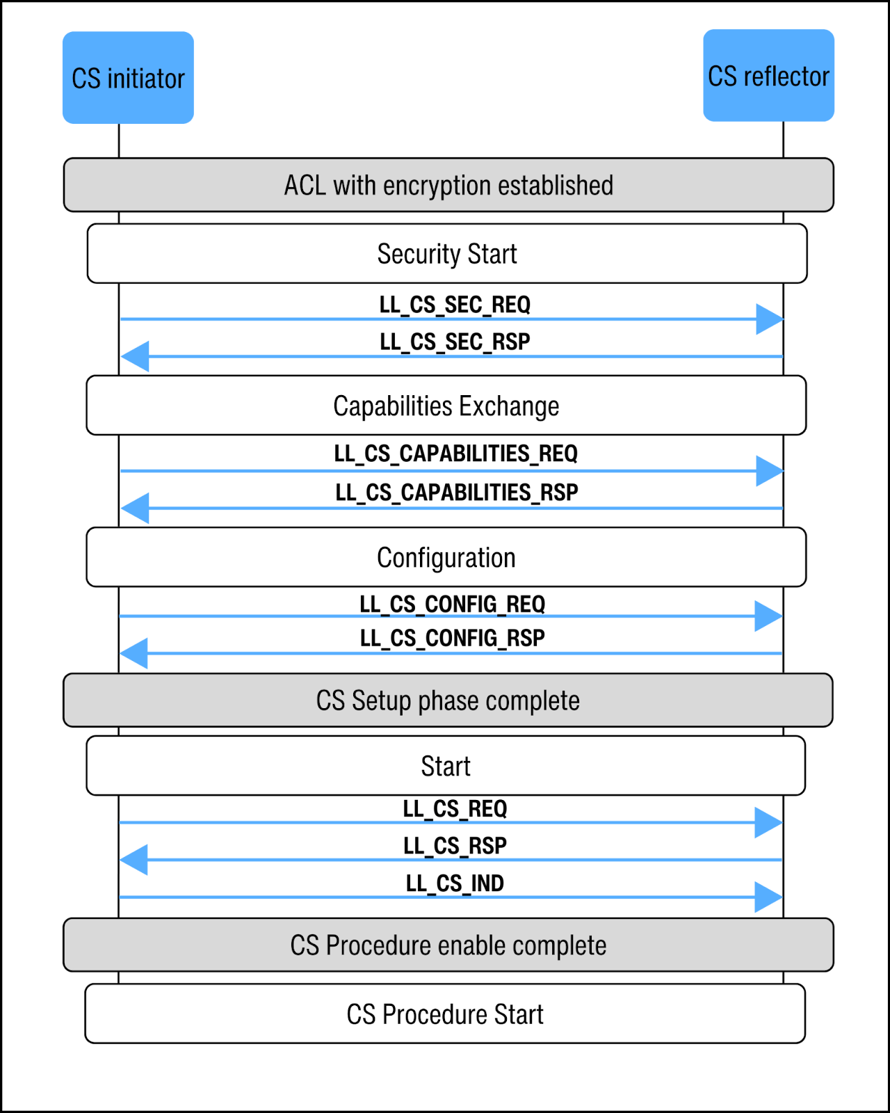
Figure 1. LL procedures to setup and enable a Central- initiated CS procedure
Channel Sounding Security Start
Channel Sounding uses its own security mechanisms, independent of the secured ACL connection it anchors to. The LL CS Security Start procedure exchanges three security parameters—CS_IV, CS_IN, and CS_PV—between the Central and Peripheral devices.
These parameters serve as inputs to the Deterministic Random Bit Generator (DRBG) function [v6.0,vol 6, part E, section 3.0]. The DRBG function provides cryptographic security, including randomizing the access address and the bit stream of Channel Sounding packets.
The procedure starts with the Central device sending its parameters (CS_IV_C, CS_IN_C, and CS_PV_C) using the LL_CS_SEC_REQ PDU. The Peripheral responds with its parameters (CS_IV_P, CS_IN_P, and CS_PV_P) using the LL_CS_SEC_RSP PDU. This exchange gives both devices matching inputs for the DRBG. With identical inputs, they can produce the same output.
Channel Sounding Capabilities Exchange
Channel Sounding is a flexible procedure with multiple configuration options. CS capabilities can differ for instance in terms of the PHYs supported, the CS modes (explained later), the accuracy of the RTT, and the maximum number of antenna paths in PBR.
Before starting the CS procedure, each device must know the other’s CS capabilities. Either the Central or Peripheral device can initiate the LL CS Capabilities procedure.
The initiating Controller sends an LL_CS_CAPABILITIES_REQ PDU, and the peer replies with an LL_CS_CAPABILITIES_RSP PDU.
Channel Sounding Configuration
The LL CS Configuration procedure selects the appropriate CS configuration set based on the capabilities of both devices. This procedure can only be performed once the capabilities of the peer device are known.
Both devices can support multiple CS configuration parameters simultaneously, with each set being uniquely identified by a configuration ID.
The LL initiates the CS Configuration procedure by sending the LL_CS_ CONFIG_REQ PDU.The initiating LL decides whether to be the CS initiator or CS reflector, and the other device automatically takes the opposite role. If the receiving device accepts the configuration parameters in the LL_CS_CONFIG_REQ PDU, it responds with the LL_CS_CONFIG_RSP PDU.
Note that LE connection roles are independent of CS roles, meaning either the Central or Peripheral device can be the CS initiator or CS reflector.
Channel Sounding Start
The LL CS Start procedure defines the number, timing, and duration of CS procedure instances. A CS procedure consists of multiple CS events. Each CS event is anchored to a connection event anchor point of the underlying LE ACL connection.
The LE CS Start procedure provides the connection event anchor point for the first CS procedure and specifies the number of LE connection intervals between consecutive CS procedures.
Either the CS initiator or reflector—regardless of whether they are in the Central or Peripheral role—can initiate the LL CS Start procedure by sending a LL_CS_REQ PDU.
If the receiving device is a Peripheral, it responds with a LL_CS_RSP PDU. If the Central receives either a LL_CS_REQ or LL_CS_RSP PDU, it replies with a LL_CS_IND PDU to start the CS procedure.
CS Ranging Methods
Round Trip Timing (RTT)
Round-trip timing uses time-of-flight (ToF) measurements to determine how long a packet takes to travel from the CS initiator to the CS reflector and back. A longer distance results in a longer ToF.
To measure ToF, the CS initiator sends a CS_SYNC packet and records the Time of Departure (ToDi). It also records the Time of Arrival (ToAi) when it receives the response from the reflector.
The CS reflector similarly records the Time of Arrival (ToAr) when it receives the packet from the CS initiator and the Time of Departure (ToDr) when it sends it back.
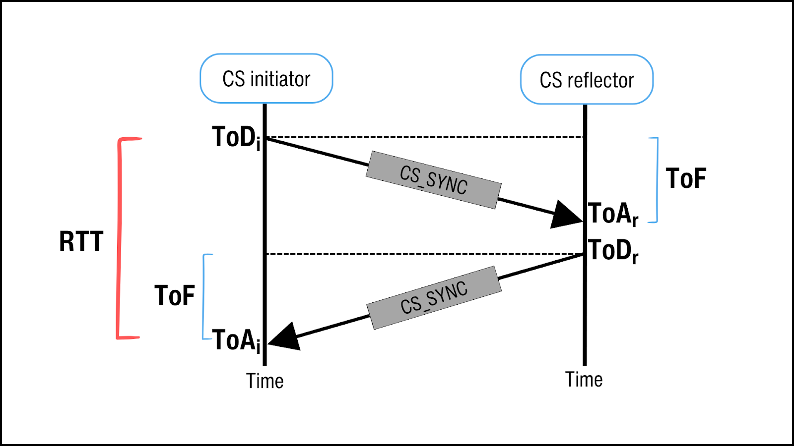 Figure 2. Distance estimation using RTT
| RTT = 2ToF = (ToAr–ToDi)+(ToAi–ToDr) D =c RTT2 |
The accuracy of these timestamps directly affects the ToF calculation. Channel Sounding offers three methods for determining the ToA timestamp, with varying levels of accuracy.
The simplest and least accurate method uses the access address of the CS_SYNC packet. A more accurate method uses fractional timing on a random or sounding sequence appended on the CS_SYNC packet. The length of this sequence can vary—the longer it is, the better the accuracy.
Phase-based Ranging (PBR)
In phase-based ranging, distance is determined by the phase difference between a transmitted signal and the same signal after it reflects back from the target.
The CS initiator sends a CS tone at a selected frequency to the CS reflector. The reflector measures the phase difference between the received tone and its local oscillator and sends the tone back. The initiator then measures the phase difference between the returned tone and its own local oscillator. These two-way phase measurements effectively cancel out the unknown initial phase offsets of the devices’ local oscillators, so precise clock synchronization between the peer devices is not required.
However, because phase “resets” after every 2(or 360 degrees), there is inherent ambiguity in the measurement. This ambiguity is resolved by performing phase measurements at multiple frequencies.
To improve accuracy, a device can use up to four antennas to create different paths for CS tones to travel between the two peer devices. By exchanging signals over different frequencies and paths, PBR gathers more data, which helps make the distance measurements more accurate.
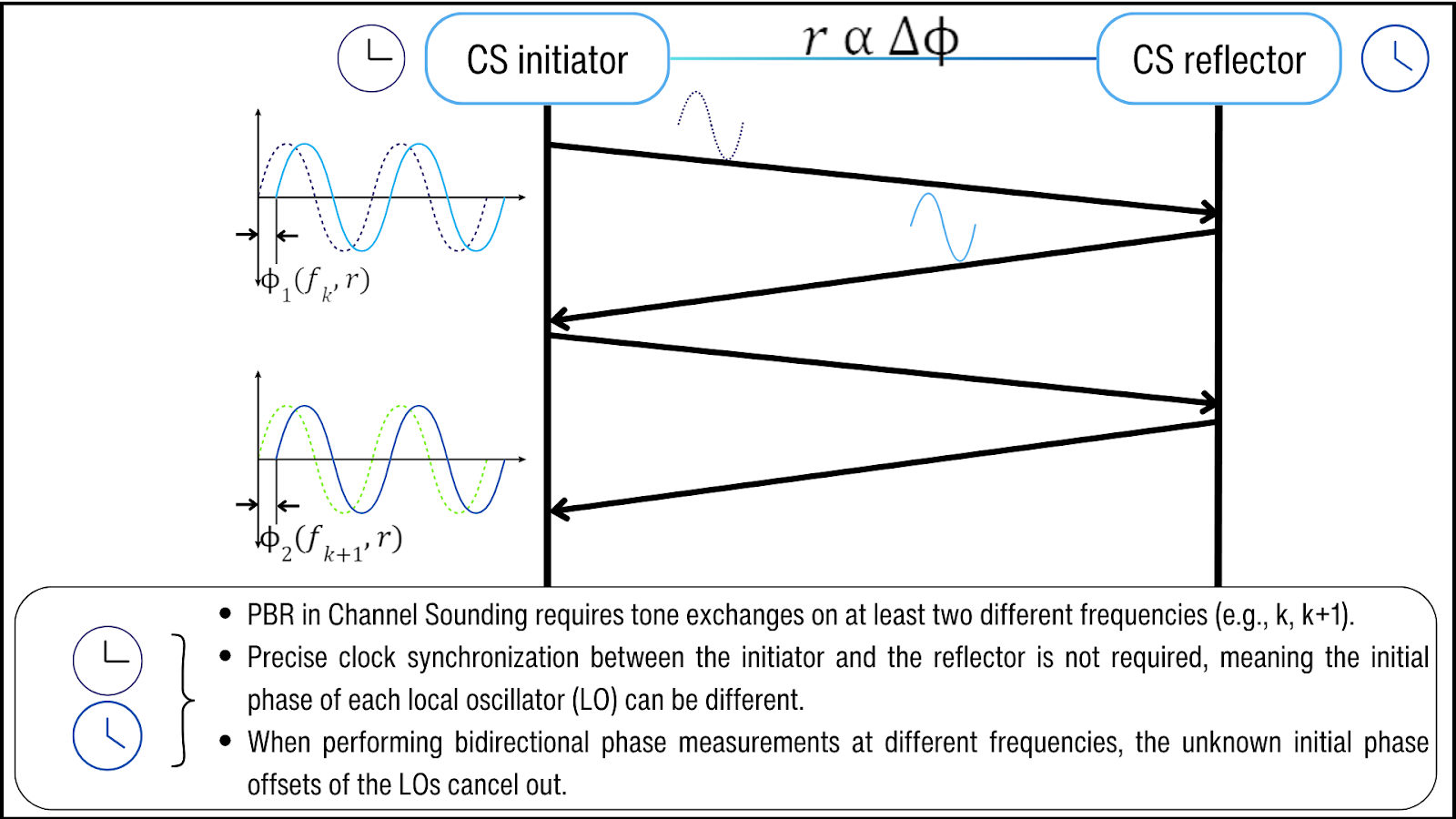 Figure 3. Distance estimation using PBR
| d2way=f.c4 |
Calibration Accuracy: FFO and FAE Table
Perfectly tuning two devices to the same frequency is not feasible. Even small frequency variations from clock drift can cause phase drift, which affects RTT and PBR measurements.
The Frequency Offset (FO) metric describes how much a Controller’s oscillator deviates from its expected frequency. The Fractional Frequency Offset (FFO) is the ratio of the frequency offset to the carrier frequency. It is calculated by dividing the frequency offset by the carrier frequency. It indicates how significant the offset is relative to the carrier.
Each frequency channel experiences its own frequency offset. The Fractional Frequency Offset Actuation Error (FAE) is a table of known frequency offset errors for each channel.
The CS initiator may access the FAE table of the CS reflector before starting RTT and PBR measurements. This table allows the initiator to understand the timing and frequency drifts between itself and the reflector. With this information, the CS initiator can compensate for these offsets and reduce measurement errors.
| Note: RTT and PBR do not calculate distance directly. RTT measures the Time of Flight of an RF signal while PBR measures the signal’s phase shifts. Both methods provide IQ data that can be used in distance measurement algorithms. The Bluetooth Channel Sounding specification does not define how to calculate distance; that is left to the implementer. |
Co-existence with Other LE communications
The CS procedure is organized into one or more CS events. Each CS event is sub-divided into one or more CS subevents, and each subevent into two or more steps.
CS events are scheduled at regular intervals based on the anchor points of the connection events of the underlying ACL connection. The offset time, in microseconds, between the LE connection event anchor point and the start of the CS event is called T_EVENT_OFFSET.
The time between the start of two consecutive CS events, measured in LE connection intervals, is called T_EVENT_INTERVAL.
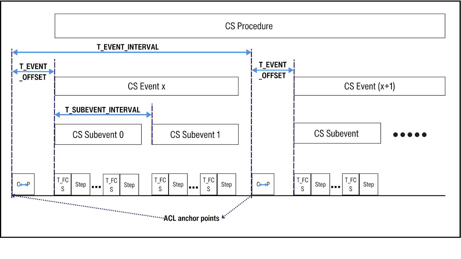
Figure 4. Channel Sounding events scheduling
CS Steps and Step Modes
A CS step is where CS exchanges take place. Either CS_SYNC packets or CS tones or both are exchanged. The CS initiator transmits first, followed by at least one response from the CS reflector.
The purpose of each step exchanges is defined by one of four CS step modes:
- Mode-0 steps: Each subevent in a CS procedure starts with one to three mode-0 steps to provide calibration information. This data helps correct timing and frequency offsets in the remaining steps of the subevent.
- Mode-1 steps: Exchange CS_SYNC packets for the RTT ranging method.
- Mode-2 steps: Exchange CS tones for the PBR method.
- Mode-3 steps: Exchange of CS extended packets, which combine a CS_SYNC and a CS tone. The initiator transmits a CS_SYNC followed by a CS tone. The reflector responds with a CS tone followed by a CS_SYNC. The packet order is fixed for each role.
Modes 0, 1, and 2 are mandatory, while Mode-3 is optional. During configuration, the Host specifies how many Mode-0 steps should appear at the start of each subevent. It also selects a Main Mode type and a Sub-Mode type, which define the sequence of CS steps in a subevent. The main mode type steps run before the sub-mode type steps.
For devices that do not support Mode-3, the Main Mode and Sub-Mode can be set to Mode-1 and Mode-2 (in either order). This allows the exchange of both CS_SYNC packets and CS tones without requiring Mode-3.
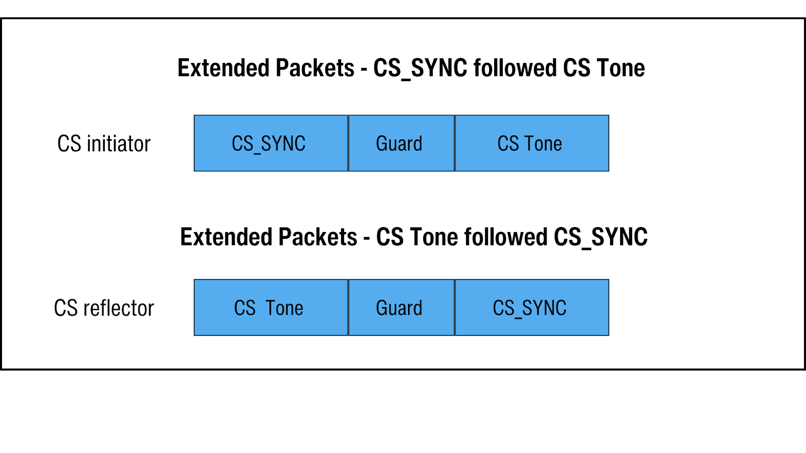 Figure 5. Channel Sounding extended packet format
CS Security features
CS provides stronger built-in security measures against attacks like man-in-the-middle (MITM), relay, and spoofing, compared to earlier Bluetooth LE positioning features, which had little to no security.
Key CS security features include:
- Every CS step is on a different channel
Each CS step uses a different channel. The CS procedure divides the Bluetooth spectrum into 72 channels, each with a 1 MHz bandwidth. A new channel is selected for every step using one of the channel selection algorithms (CSA #3a, CSA #3b, or CSA #3c).
| Note:Using 1 MHz channels, rather than the standard 2 MHz, reduces distance ambiguity for adjacent PBR signals, making signal overlap issues start at 150 m instead of 75 m. |
- Randomized Access Addresses
Each CS packet has a unique, cryptographically generated access address, so the packet’s “name” changes at every step. This makes it more difficult for attackers to spoof packets.
- Randomized Transmission Patterns
In PBR, multiple antennas create different paths for tone exchanges between the CS initiator and CS reflector. During each mode-2 or mode-3 step, tones are exchanged over all the configured antenna paths in a random order before moving to the next step. This randomness makes an eavesdropping attack difficult.
- Randomization of Bit Streams
A CS_SYNC packet can optionally include a random sequence or a sounding sequence, both of which add unpredictability to make the packet harder for attackers to analyze. The random sequence is generated using a DRBG function, with inputs shared exclusively between the CS initiator and CS reflector during the CS Security Start procedure. The sounding sequence, on the other hand, contains pseudo-random markers.
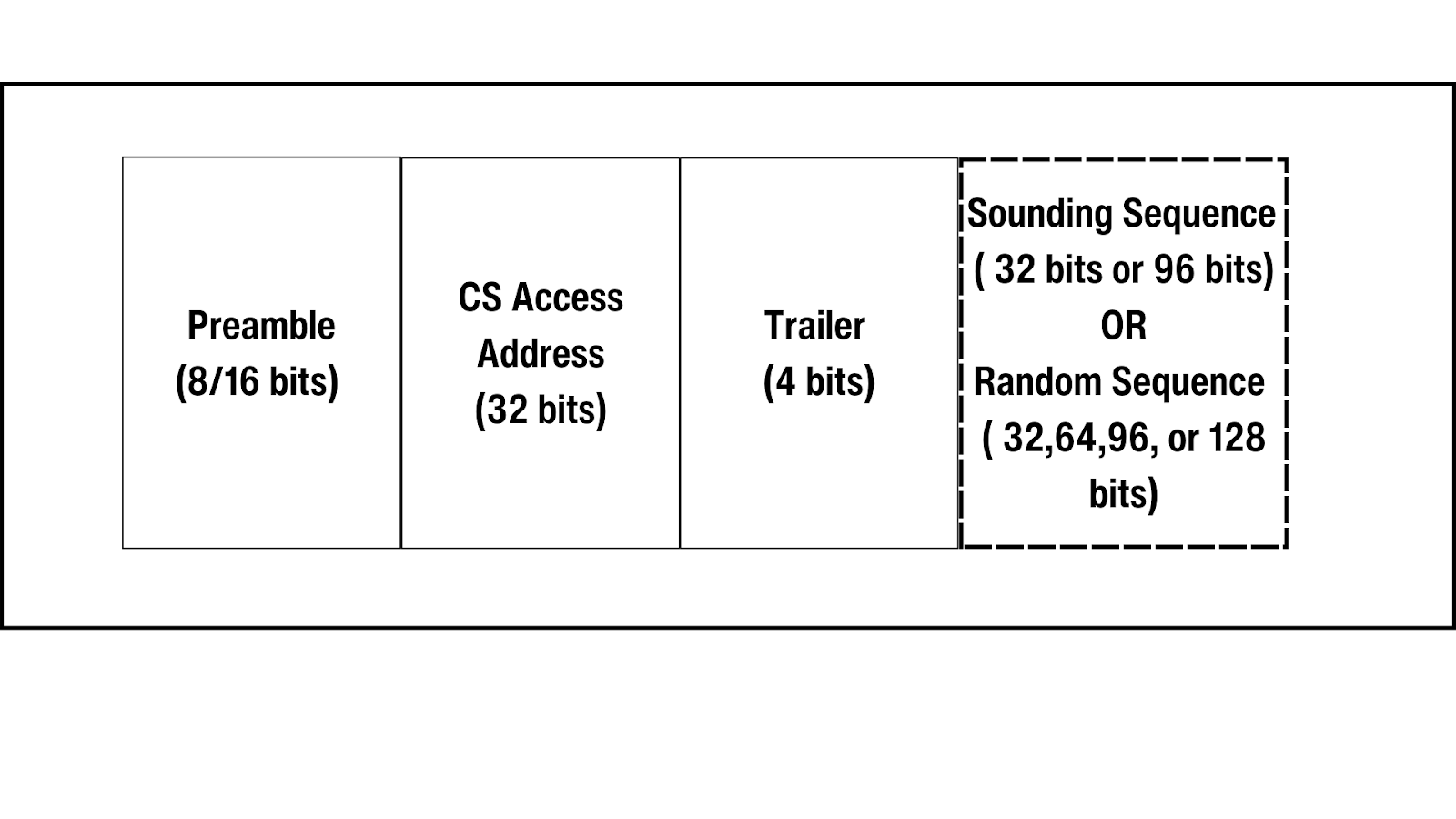
Figure 6. Channel Sounding CS_SYNC packet format
- Randomization of Tone Extension Slot Transmissions
In PBR step modes-2 and 3, a reserved tone extension slot transmits at intervals randomly chosen by the DRBG. This randomization makes transmission patterns harder for attackers to predict.
- Normalized Attack Detector Metric (NADM)
Manipulation of a CS signal leaves detectable imprints. The NADM engine analyzes these signals to assess the likelihood of an attack by comparing them against known attack patterns. While NADM provides a standardized report, it’s up to the application to decide on any response.
- Cross-checking of PBR with RTT
RTT and PBR methods can be combined in the same CS subevent or in the same CS step using step mode-3. When these two ranging methods are combined, their independent estimates must match. This means that if an attacker manipulates PBR, they must also simultaneously manipulate RTT with the same level of error; otherwise, NADM will detect the inconsistency and flag the attack.
| Note:RTT is highly secure because time is irreversible. Also, a random sequence or a sounding sequence can be appended to the CS_SYNC PDU to make it hard for attackers to predict or manipulate the signal. |
- LE 2M 2BT PHY
The LE 2M 2BT PHY is a new PHY designed for Channel Sounding. It has a Bandwidth-Time (BT) value of 2, which is higher than the 0.5 BT used in other LE radio PHYs. This higher BT value creates shorter, faster pulses. Because the signal duration is shorter, it changes more rapidly, limiting the time window for an attacker to analyze or capture the signal.
- Vendor-specific Security Measures
Implementers can add vendor-specific security features to augment CS security.
CS vs RSSI vs AOA
Bluetooth provides direction-finding and distance estimation capabilities to the LE Controller. The Bluetooth Core Specification 5.1 introduced AoA and AoD methods to enable the controller to use angle information from multiple anchors for localization.
RSSI uses a path loss model based on signal strength degradation for coarse distance estimation. While it’s simple and widely used, it is highly susceptible to multipath effects, which can cause significant inaccuracies, especially over long distances.
Channel Sounding offers a more secure and precise alternative. Although it doesn’t replace RSSI, it can complement it in certain applications, improving overall accuracy.
| Parameter | Received Signal Strength Indicator (RSSI) | Angle of Arrival / Angle of Departure (AoA) / (AoD) | Channel Sounding (CS) |
| Purpose | Distance estimation | Direction finding | Distance estimation |
| Connectivity | Connection-Oriented and Connectionless | Connection-Oriented and Connectionless | Only Connection-Oriented |
| Antenna | Single antenna | Antenna array required | Antenna array not required but improves PBR accuracy |
| PHY support | All PHYs supported | Only LE Uncoded PHYs | LE 2M 2BT PHY |
| Advantages | Ubiquitous and easy to implement solution in existing LE products. | Interoperable, scalable solution for positioning systems such as real-time locating systems (RTLS) and indoor positioning systems (IPS). | Provides high accuracy with multi-level security mechanisms, ensuring secure and precise ranging systems. |
Table 1. Comparison of RSSI, AoA and CS
Conclusion
Channel Sounding gives the LE controller the ability to use RTT and PBR ranging methods to generate data that can be used to calculate the distance from its connected peer device. It includes several built-in security features to support secure fine-ranging.
With the release of Bluetooth Core Specification 6.0, Bluetooth developers can now take advantage of Channel Sounding’s precise distance estimation capability to build secure, accurate, and interoperable fine-ranging systems between connected Bluetooth LE devices.
References
- “Core Specification 6.0” Bluetooth.com, www.bluetooth.com/specifications/specs/core-specification-6-0/. Accessed 16 Oct 2024.
- “Bluetooth Core Specification 6.0 Feature Overview” Bluetooth.com, www.bluetooth.com/core-specification-6-feature-overview/. Accessed 16 Oct 2024.
- “Bluetooth Core Specification 5.1 Feature Overview” Bluetooth.com, www.bluetooth.com/bluetooth-resources/bluetooth-core-specification-v5-1-feature-overview/. Accessed 16 Oct 2024.