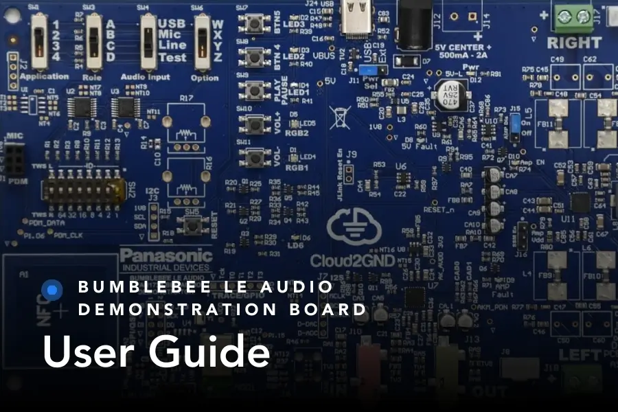
INTRODUCTION
The Cloud2GND Bumblebee LE Audio Demonstrator, featuring the Panasonic PAN1783 Bluetooth LE module, demonstrates high-fidelity Bluetooth LE Audio applications. The Bumblebee board includes amplifiers, drivers, audio connectors, and other components to provide an out-of-box Bluetooth LE Audio experience. The board is configurable for various use cases, such as point to point connected audio, stereo audio to left/right devices (aka “True Wireless Stereo”), and audio broadcast (AuracastTM ). This user’s guide explains how to configure and operate the board for several example use cases.
TABLE OF CONTENTS
INTRODUCTION
OVERVIEW
SETTINGS
BUTTONS
LEDS
INPUTS/OUTPUTS
EXAMPLE: TWS EARBUDS
EXAMPLE: AURACASTTM
EXAMPLE: WALKIE-TALKIE
EXAMPLE: HEADSET WITH MICROPHONE
UPDATING BUMBLEBEE FIRMWARE
REVISION HISTORY
TRADEMARKS
OVERVIEW
The Bumblebee LE Audio demonstrator includes the main board, referred to as the Bumblebee
board, and a MEMS microphone daughterboard.
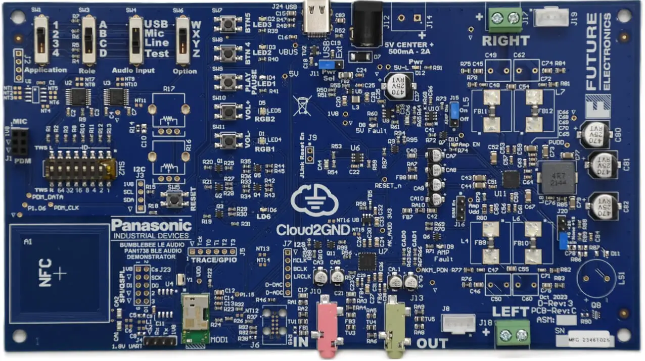
Bumblebee Board
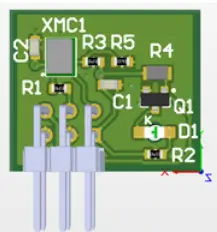
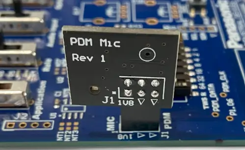
MEMS PDM Microphone Daughterboard
The microphone board connects to J1 – MIC/PDM on the left edge of the Bumblebee board. The
board is oriented with the triangle markers aligned, as shown below.
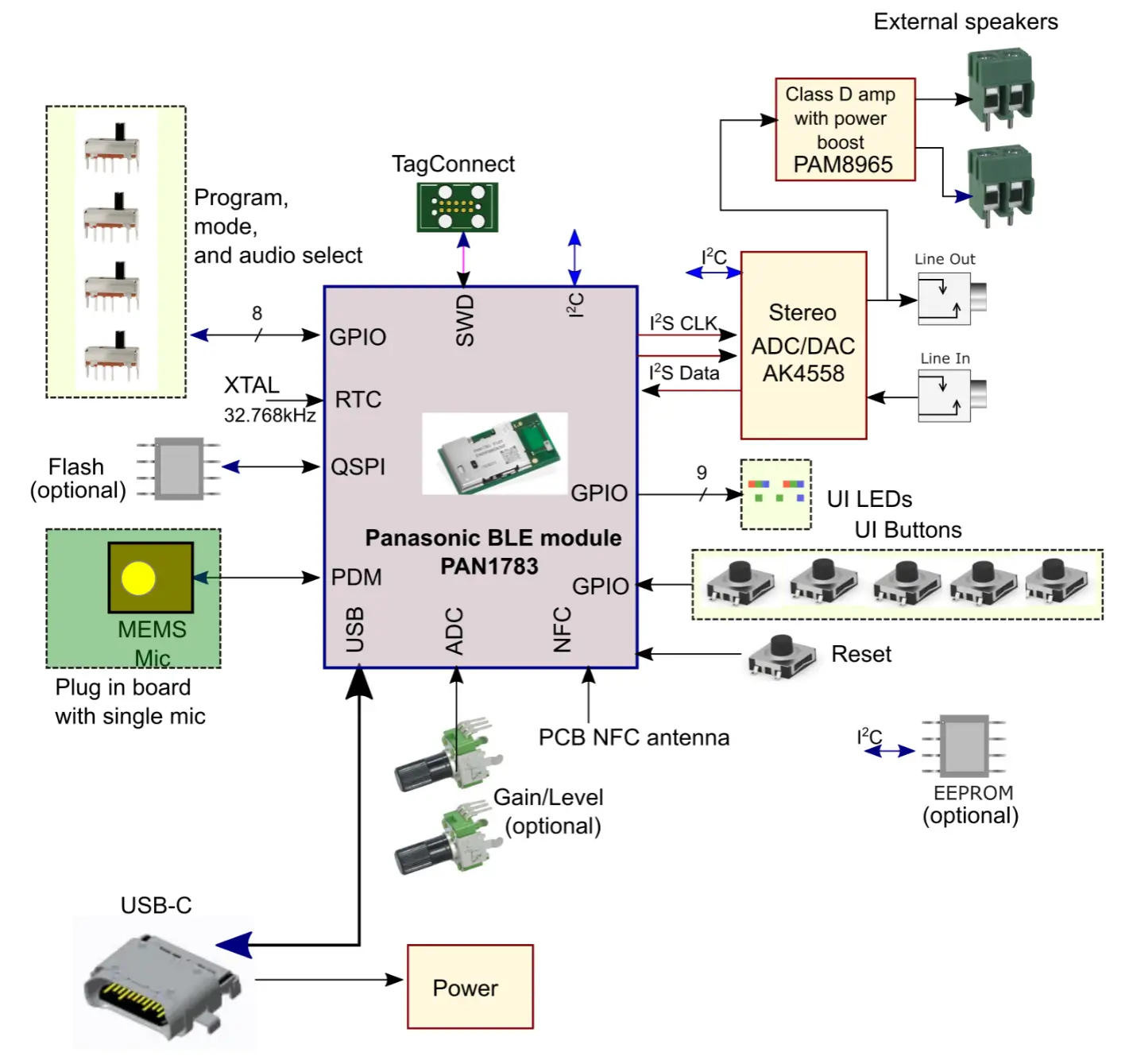
The following illustration shows a block diagram of the completed system’s main components:
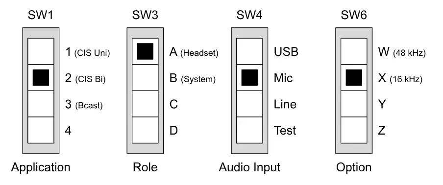
SETTINGS
The Bumblebee board is configured using various switches and jumpers. The information below
shows the behavior of individual settings. Not all combinations of settings are valid. See the
detailed configuration and operating instructions in subsequent sections for information on
supported combinations.
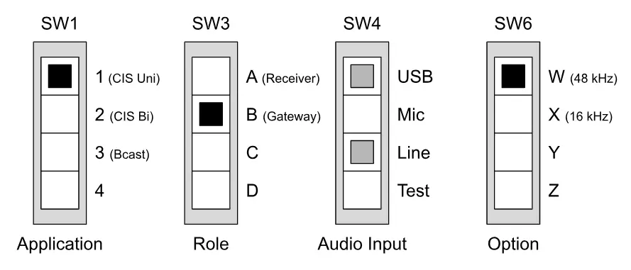
SW1 – Application
| Setting | Description |
| 1 | Unidirectional Connected |
| 2 | Bi-directional Connected |
| 3 | Unidirectional Broadcast |
| 4 | Reserved |
SW3 – Role
| Setting | Description |
| A | Behavior varies by application |
| B | Behavior varies by application |
| C | Reserved |
| D | Reserved |
SW4 – Audio Input
| Setting | Description |
| USB | USB connector |
| Mic | MEMS microphone |
| Line | Line In connector |
| Test | Reserved |
SW6 – Option
| Setting | Description |
| W | 48 kHz sampling |
| X | 16 kHz sampling |
| Y | Reserved |
| Z | Reserved |
SW2 – TWS / ID
| Bit | Description |
| 7 | Received Audio Channel ON=Left, OFF=Right |
| 6:0 | Board ID (for pairing) |
J11 – Pwr Sel
| Bit | Description |
| USB | Powered over USB |
| Ext | Powered over 5V connector |
J15 – AMP Dis
| Option | Description |
| Off | AMP is disabled |
| On | AMP is controlled by firmware |
| Open | AMP is always on |
J20 – Gain
| Option | Description |
| +6 | +6 dB |
| +26 | +26 dB |
| Open | +18 dB |
BUTTONS
| Button | Description |
| BTN4 (SW8) | Function depends on configuration. |
| BTN5 (SW7) | Function depends on configuration. |
| PLAY/PAUSE (SW9) | Causes audio to start or stop. Affected board depends on configuration. |
| RESET (SW5) | Resets the Bumblebee board. Must be pressed to detect configuration changes. |
| VOL+ (SW10) | Increases the volume. Affected board depends on configuration. |
| VOL- (SW11) | Decreases the volume. Affected board depends on configuration. |
LEDS
| LED | Description |
| 5V Pwr | Solid Green – 5V power is on |
| 5V Fault | Solid Red – Amplifier current exceeded USB limit |
| AMP En | Solid Green – Audio amplifier is enabled |
| AMP Fault | Solid Red – FLT pin of PAM8965 active |
| LED1 | Solid Blue – Audio streaming Slow Blink – Connected/synchronized to device, no audio is streaming Fast Blink – Searching for device |
| LED2 | Solid Green – Audio synchronization achieved |
| LED3 | Blinking Green 1/sec – The audio application is operating normally Solid Green, off, or irregular blinking – Abnormal operation |
| LD6 | Solid Green – Hardware CODEC and amplifier circuit are enabled |
| MIC En | Solid Red – Mic is enabled |
| RGB1 (LED4) | Solid Blue – Operating as a left-channel receiver Solid Magenta – Operating as a right-channel receiver Solid Green – Operating as a gateway Blinking Red – Invalid switch setting (see also RGB2) Solid Red- Fault has occurred, needs reset |
| RGB2 (LED5) | Blinking Red – Invalid switch setting (see also RGB1) Solid Red – System crash |
INPUTS/OUTPUTS
| Port | Description |
| 5V (J12) | DC 5V power connector, 2A |
| LEFT (J18), J8 | Left speaker connectors. All configurations send the same audio to all outputs (left and right). |
| LINE IN | Stereo audio line in. Can be used as an audio source in some configurations. |
| LINE OUT | The audio line out port is active in all configurations where a board is receiving audio. The audio only contains the mono channel that is playing duplicated as both the left and right stereo channels. |
| NFC | The NFC port sends a URL to devices that support near field communication. |
| RIGHT (J17), J19 | Right speaker connectors. All configurations send the same audio to all outputs (left and right). |
| USB | The USB port can be used for power and as an audio source/sink in some configurations. |
J8/J19 Speaker Connectors (TE 1735446-4)
| Pin | Description |
| 1 | Speaker + |
| 2 | Speaker – |
| 3 | Speaker + (shorted to pin 1) |
| 4 | Speaker – (shorted to pin 2) |
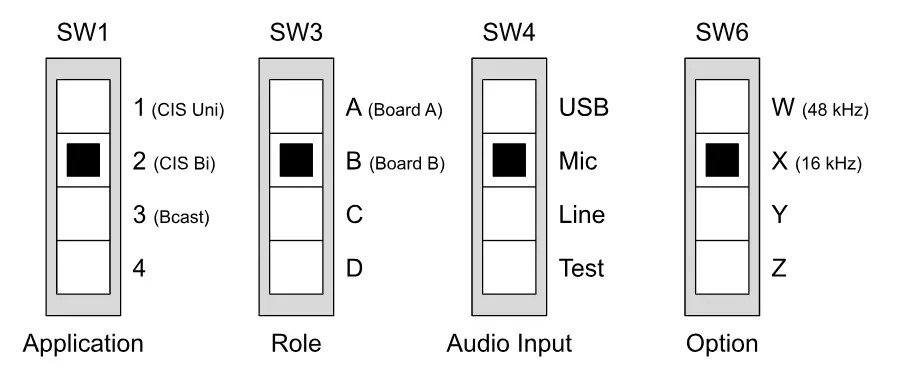
EXAMPLE: TWS EARBUDS
In this example, a board acting as an audio gateway uses Bluetooth LE Connected Isochronous
Streams (CIS) to send audio to two receiver boards in a true wireless stereo (TWS) configuration.
Each receiver board is configured to accept a specific audio channel – left or right.
Gateway Board Configuration
SW2 DIP Bits 6:0 – ID = (all boards set to the same ID)
Connect an audio source to LINE IN or USB, as selected above.
Receiver Board Configuration
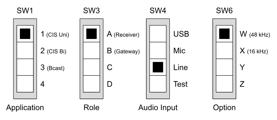
Left Receiver
- SW2 DIP Bit 7 – TWS L/R = L (ON)
Right Receiver
- SW2 DIP Bit 7 – TWS L/R = R (OFF)
SW2 DIP Bits 6:0 – ID = (all boards set to the same ID)
Connect a speaker to any speaker connector (J8, J17, J18, or J19)
Operation
Setting changes on each board will not take effect until that board is reset. Reset each board by
pressing RESET.
With the boards configured as shown, the gateway will sample audio from the selected input port
and send the left channel to the left receiver and the right channel to the right receiver. After the
gateway connects to the receiver boards, the receivers will play the left or right audio, according to configuration. Because each receiver only receives one audio channel, each plays the same audio to
all of its outputs.
The VOL+ and VOL- buttons on the gateway or receivers control the volume of all receivers.
Similarly, the Play/Pause button and Mute button (BTN5) on any device control whether audio is
enabled on all devices. After pressing Mute (BTN5), the VOL+ and VOL- buttons can be used to
unmute the audio.
LE Audio Configuration
Unidirectional CIS: 16-bit 48 kHz audio sampling, 96 kbps LC3 encoding (per channel)
EXAMPLE: AURACASTTM
In this example, a board acting as an audio gateway uses Bluetooth LE Broadcast Isochronous
Streams (BIS) to send two channels of audio to an arbitrary number of receiver boards. Each
receiver board is configured during boot to play a specific audio channel – left or right. A button,
BTN4, can be used on a receiver to switch channels while actively receiving audio data.
Gateway Board Configuration
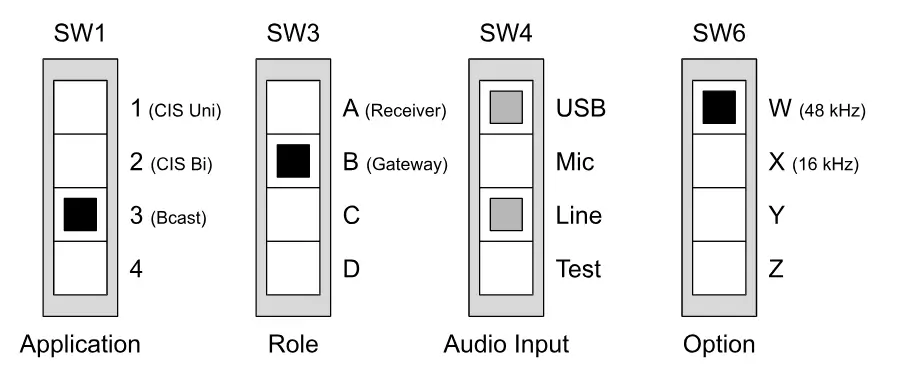
SW2 DIP Bits 6:0 – ID = (all boards set to the same ID)
Connect an audio source to LINE IN or USB, as selected above.
Receiver Board Configuration
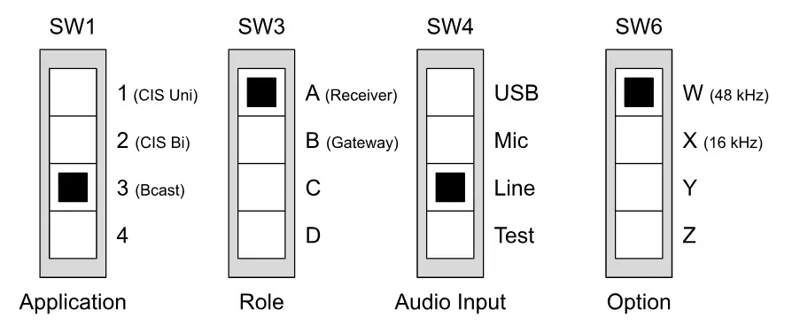
Left Receiver
- SW2 DIP Bit 7 – TWS L/R = L (ON)
Right Receiver
- SW2 DIP Bit 7 – TWS L/R = R (OFF)
SW2 DIP Bits 6:0 – ID = (all boards set to the same ID)
Connect a speaker to any speaker connector (J8, J17, J18, or J19)
Operation
Setting changes on each board will not take effect until that board is reset. Reset each board by
pressing RESET.
With the boards configured as shown, the gateway will sample audio from the selected port and
broadcast it using BIS streams. After the receivers synchronize to the gateway board, the receivers
will play the audio from the gateway. Left receivers will play the left channel and right receivers will
play the right channel. Pressing BTN4 on a receiver toggles the left/right channel for that receiver by triggering a synchronization to the BIS stream for the other channel. The left/right stream could
represent left/right stereo audio information or it could be two distinct audio streams such as
English/Spanish audio.
Pressing the Play/Pause button on the gateway board pauses or resumes audio for all receivers.
The VOL+ and VOL- buttons have no effect.
The Play/Pause, VOL+, and VOL- buttons on a receiver only affect that receiver.
If Multiple Broadcasters are Present…
If multiple broadcasters are present when a receiver starts, the receiver synchronizes to the
broadcaster that has a matching ID value. If none have a matching ID, then the receiver
synchronizes to any Bumblebee broadcaster it finds.
At any point, pressing BTN5 on the receiver causes the receiver to search for a different Bumblebee
broadcaster – one that it has not synchronized to previously – and synchronize to it. If the receiver
has already synchronized to all available broadcasters, then the receiver clears its history and
behaves as if freshly booted.
LE Audio Configuration
Unidirectional BIS: 16-bit 48 kHz audio sampling, 96 kbps LC3 encoding (per channel)
EXAMPLE: WALKIE-TALKIE
In this example, two boards use a Bluetooth LE Connected Isochronous Stream (CIS) to send
bi-directional audio.
Board A Configuration
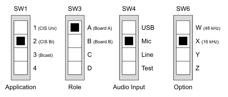
SW2 DIP Bit 7 – TWS L/R = L (ON)
Connect a speaker to any speaker connector (J8, J17, J18, or J19)
SW2 DIP Bits 6:0 – ID = (both boards set to the same ID)
Board B Configuration
SW2 DIP Bit 7 – TWS L/R = L (ON)
Connect a speaker to any speaker connector (J8, J17, J18, or J19)
SW2 DIP Bits 6:0 – ID = (both boards set to the same ID)
SW2 DIP Bit 7 – TWS L/R = L (ON)
Connect a speaker to any speaker connector (J8, J17, J18, or J19)
SW2 DIP Bits 6:0 – ID = (both boards set to the same ID)
Operation
Setting changes on each board will not take effect until that board is reset. Reset each board by
pressing RESET.
With the boards configured as shown, each board will continuously sample the audio from its MIC
input and send it to the other board, where it is played to all outputs. The VOL+ and VOL- buttons
on Board A adjust the volume output of Board A.
LE Audio Configuration
Bi-directional CIS: 16-bit, 16 kHz audio sampling, 64 kbps LC3 encoding
Using 48 kHz Sampling
This example also supports single-channel, 48kHz audio sampling. To use 48 kHz sampling, update
the board settings as follows:
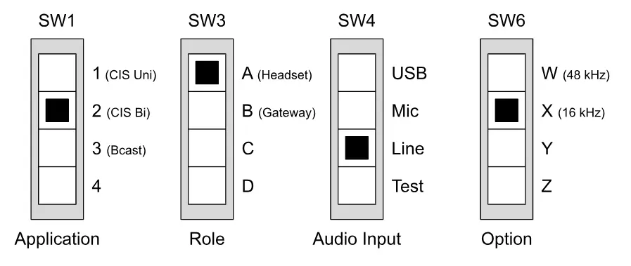
Board A Configuration (48 kHz Sampling)
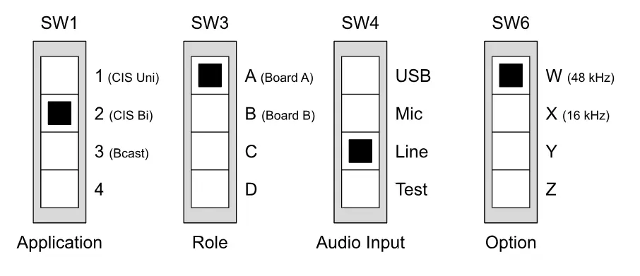
Board B Configuration (48 kHz Sampling)
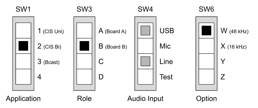
Board A will sample the LINE IN port and transmit the channel of audio indicated by Board B’s
channel selection setting. Board B will sample LINE IN or USB, as selected, and transmit the audio
channel to board A per board A’s channel selection setting. The VOL+ and VOL- buttons adjust the
volume output of the local board.
When using 48 kHz sampling with USB selected on board B, board B’s USB port supports audio
input and output as a USB device. (The USB port does not support host mode.)
Note: USB is only supported when the Role switch is set to B.
LE Audio Configuration
Bi-directional CIS: 16-bit, 48 kHz audio sampling, 96 kbps LC3 encoding
EXAMPLE: HEADSET WITH MICROPHONE
In this example, a board acting as a gaming system uses Connected Isochronous Streams (CIS) to
send audio to a set of devices acting as a TWS headset and to receive microphone audio from one of
the headset devices.
Note: All audio in this example uses 16 kHz sampling.
Gaming System Board Configuration
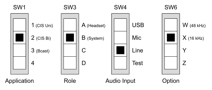
SW2 DIP Bit 7 – TWS L/R = L (ON)
Connect a speaker to any speaker connector (J8, J17, J18, or J19)
SW2 DIP Bits 6:0 – ID = (all boards set to the same ID)
Left Headset Board Configuration
SW2 DIP Bit 7 – TWS L/R = L (ON)
Connect a speaker to any speaker connector (J8, J17, J18, or J19)
SW2 DIP Bits 6:0 – ID = (all boards set to the same ID)
Right Headset Board Configuration
Operation
Setting changes on each board will not take effect until that board is reset. Reset each board by
pressing RESET
With the boards configured as shown, the gaming system board will sample audio from the selected
source and send the left channel to the left headset board and the right channel to the right headset
board. After the gaming system board connects to the headset boards, the boards will play the audio
from the gaming system. Because each headset board only receives one audio channel, each plays
the same audio to all of its outputs. The left headset board will sample its microphone and send it to
the gaming system board, where it is played to all outputs.
The VOL+ and VOL- buttons on the gaming system board and headset boards control the volume of
both headset boards.
LE Audio Configuration
Bi-directional CIS: 16-bit, 16 kHz audio sampling, 64 kbps LC3 encoding (per channel)
UPDATING BUMBLEBEE FIRMWARE
The Bumblebee board comes with firmware that provides the functionality described in this User’s
Guide. Updates and additional features may be provided in firmware releases by Cloud2GND.
Note: Only official Cloud2GND releases are supported by the Bumblebee board. Programming any
other code may cause the board to become unusable.
Updating the Bumblebee board firmware requires using a smartphone that is supported by the nRF
Connect Device Manager application. This application communicates with the Bumblebee board and
requires that the board be booted in over-the-air (OTA) update mode. Please follow the instructions
in this section to update the Bumblebee firmware.
Instructions for Updating the Bumblebee Firmware
Install the nRF Connect Device Manager application on your mobile device.
Download the Bumblebee board firmware file (e.g., Cloud2GND_Bumblebee_FWv1.bin) to your
mobile device.
Put the Bumblebee board in OTA update mode.
- Press and hold BTN4.
- Press RESET.
- Continue holding BTN4 until LED2 starts flashing quickly. (LED2 should start flashing
within 5 seconds.) - Release BTN4. LED2 will continue flashing quickly and LED3 will flash slowly.
Use the nRF Connect Device Manager application to program the board.
1. Open the nRF Connect Device Manager application. The application will automatically search for the Bumblebee board. When found, the Bumblebee board will be listed.
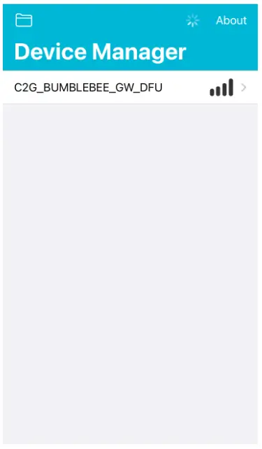
2. Select the Bumblebee board.
3. Select the “Image” view.
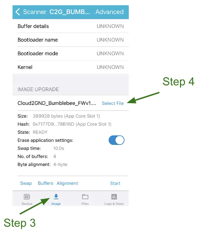
4. Use “Select File” on the Image view to select the firmware file you downloaded previously.
5. Press “Start” and then “Confirm Only”.
6. The nRF Connect Device Manager application will program the firmware. Do not power off or
reset the Bumblebee board until the program operation is complete. The board will
automatically reset and begin normal operation.
REVISION HISTORY
| Revision | Date | Description |
| 1.0 | 1/10/2024 | Initial release. |
LEGAL NOTICE
All contents © 2023 Cloud2GND, LLC and its subsidiaries.
This document and its contents are intended only for use with Cloud2GND products or in relation to
Cloud2GND services. Use of this document or its contents in any other manner violates these terms
and duplication, reproduction, or any other use of this document is expressly prohibited without
prior written permission.
ALL INFORMATION IS PROVIDED AS-IS. CLOUD2GND MAKES NO REPRESENTATIONS OR
WARRANTIES ON ANY KIND RELATED TO THE INFORMATION CONTAINED IN THIS DOCUMENT. IN
NO EVENT SHALL CLOUD2GND OR ITS SUBSIDIARIES, PARTNERS, OR REPRESENTATIVES BE
LIABLE FOR INDIRECT, SPECIAL, PUNITIVE, INCIDENTAL, OR CONSEQUENTIAL LOSS, DAMAGE,
COST, OR EXPENSE OF ANY KIND RELATED TO THIS INFORMATION OR ITS USE.
For additional information please contact [email protected]
TRADEMARKS
The Bluetooth® word mark and logos are registered trademarks owned by Bluetooth SIG, Inc. The
AuracastTM word mark and logos are trademarks owned by Bluetooth SIG, Inc. Any use of such
marks by Cloud2GND is under license. Other trademarks and trade names are those of their
respective owners.